· AtlasPCB Engineering · Engineering · 10 min read
Rogers RO4003C vs RO4350B: Choosing the Right Rogers Material for Your RF PCB
A direct engineering comparison of Rogers RO4003C and RO4350B for RF PCB applications. Covers dielectric properties, loss performance, processing differences, cost, and the specific frequency ranges and circuit types where each material delivers optimal results.
Quick Answer
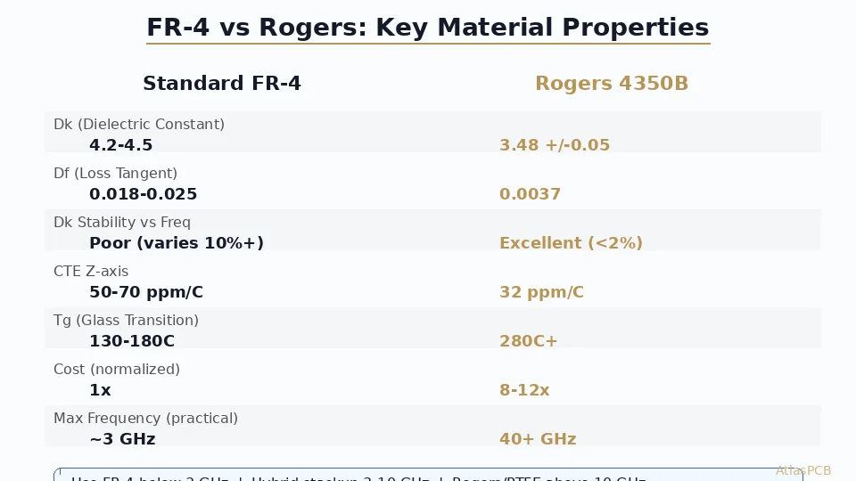
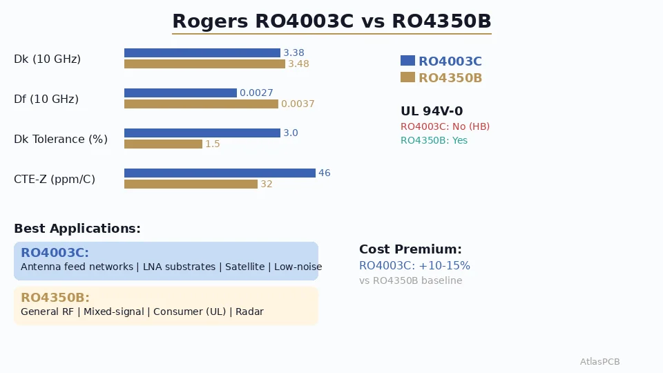
Choose RO4350B (Dk 3.48, Df 0.0037) for most RF applications up to 40 GHz where UL 94V-0 flame retardancy is required and standard FR-4-compatible processing is essential. Choose RO4003C (Dk 3.38, Df 0.0027) when your loss budget demands 27% lower dissipation factor and you can work without UL 94V-0 rating — typically for antenna feed networks, low-noise amplifier substrates, and satellite communication circuits where every 0.001 Df matters.
Quick Decision: RO4003C vs RO4350B
| Parameter | RO4003C | RO4350B |
|---|---|---|
| Dk (10 GHz) | 3.38 ± 0.05 | 3.48 ± 0.05 |
| Df (10 GHz) | 0.0027 | 0.0037 |
| Dk tolerance | ±3% | ±1.5% |
| UL 94V-0 | No (HB only) | Yes |
| Thermal conductivity | 0.71 W/m·K | 0.69 W/m·K |
| CTE (X/Y) | 11/14 ppm/°C | 10/12 ppm/°C |
| CTE (Z) | 46 ppm/°C | 32 ppm/°C |
| Processing | FR-4 compatible | FR-4 compatible |
| Relative cost | 1.10-1.15x | 1.0x (baseline) |
| Best for | Lowest loss, antennas | General RF, mixed-signal |
The one-sentence answer: If your design needs UL certification or you prioritize impedance tolerance over absolute loss, use RO4350B. If every 0.001 Df of loss reduction improves your system performance (antenna gain, receiver noise figure), use RO4003C.
Where the 0.001 Df Actually Matters
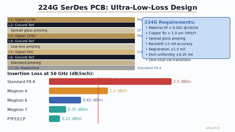
The difference between 0.0027 and 0.0037 dissipation factor sounds trivial on paper, but the impact compounds across physical length, frequency, and array elements. At 28 GHz, a 50mm microstrip on RO4350B has approximately 0.18 dB/cm insertion loss versus 0.14 dB/cm on RO4003C. Over a 64-element phased array feed network with typical 150mm average path length, that difference becomes 0.6 dB of additional loss per element — which translates directly to 0.6 dB lower antenna gain or equivalently 13% less effective radiated power across the array.
For single-element designs, filters, or short transmission lines under 30mm, the 0.001 Df difference is essentially invisible in system performance. A typical bandpass filter on RO4350B at 10 GHz shows insertion loss within 0.1 dB of the same design on RO4003C, well within measurement uncertainty. This is why RO4350B dominates the general RF market — for most circuits, the performance difference simply does not justify the added cost or supply chain complexity.
The crossover frequency where RO4003C starts delivering measurable system benefit depends on your specific topology, but as a practical rule: below 10 GHz, you will not detect the difference in any real measurement. Between 10-20 GHz, the benefit appears only in long transmission lines or high-element-count arrays. Above 20 GHz, RO4003C becomes the clear choice for loss-sensitive paths.
RF MATERIAL EXPERTISE
Need Help Choosing Between RO4003C and RO4350B?
Our RF engineers simulate both materials in your actual stackup before production. Get loss budget analysis and material recommendation with your quote.
Get Material Recommendation ›Dk Tolerance: The Hidden Differentiator
Rogers specifies RO4350B with ±1.5% Dk tolerance versus ±3% for RO4003C. In absolute terms, that means RO4350B delivers Dk between 3.43-3.53 while RO4003C can range from 3.28-3.48. For impedance-controlled transmission lines, this tolerance directly affects your impedance repeatability panel-to-panel.
Consider a 50-ohm microstrip designed for Dk 3.38 on RO4003C: at the material tolerance extremes, your impedance can swing from 48.5 to 51.8 ohms purely from Dk variation — that is already ±3.3% impedance tolerance from material alone, before adding manufacturing etch and thickness variations. The same line on RO4350B (Dk 3.48, ±1.5%) produces impedance variation of only ±1.7% from material Dk — giving your fabricator more headroom to deliver tight overall impedance tolerance.
This matters enormously for narrowband filter designs, coupled-line couplers, and balanced power dividers where the absolute Dk value determines center frequency. A Wilkinson divider designed for 5.8 GHz on RO4003C might shift to 5.7 or 5.9 GHz at material tolerance extremes. The same divider on RO4350B stays within ±30 MHz. In our production experience, we consistently achieve ±5% impedance on RO4350B versus ±7-8% on RO4003C for equivalent board complexity — the tighter material Dk is the primary reason.
For broadband applications (wideband antennas, traveling wave amplifiers, distributed structures), the absolute Dk tolerance matters less because the design accommodates a range of effective dielectric constants by nature. This is another reason antenna designers often prefer RO4003C — they get the loss benefit without suffering from the wider Dk tolerance.
UL 94V-0: When It Is and Is Not a Constraint
RO4350B includes halogenated flame retardant additives that provide UL 94V-0 certification. RO4003C achieves only UL 94HB (horizontal burn) rating in its standard formulation. This certification difference has significant implications for certain product categories but is irrelevant for others.
Products requiring UL 94V-0 include consumer electronics destined for US/EU markets (most CE and UL-listed products), telecom infrastructure equipment, industrial control systems, and any product where flammability certification is part of the regulatory submission. If your end product requires UL listing, using RO4003C may require additional system-level flame barrier solutions or force you to the UL-rated variant.
Products where UL 94V-0 is typically not required include military and aerospace equipment (governed by MIL-specs, not UL), satellite payloads, test and measurement equipment, and research/prototype boards. In our experience with aerospace and defense RF customers, approximately 70% specify RO4003C because the loss performance is their priority and UL certification is simply not applicable to their product category.
The practical implication: if you are building a commercial 5G small cell or WiFi 7 access point that needs UL listing, RO4350B is the safer choice. If you are building a radar module for defense or a satellite transponder, RO4003C gives you lower loss without the irrelevant flame retardancy overhead.
ROGERS MATERIAL IN STOCK
Both RO4003C and RO4350B Ready for Production
We stock 6.6mil, 10mil, 20mil, and 30mil cores in both materials. No material lead time delay on your RF prototype.
View RF PCB Capabilities ›Hybrid Stackup Strategies: Best of Both Worlds
The most cost-effective and performance-optimized approach for complex RF/digital systems combines both materials in a single board. A typical 8-layer hybrid might use RO4003C on the primary antenna feed layer where loss directly affects system performance, RO4350B on a secondary RF layer handling the transceiver IF chain where UL compliance matters, and standard FR-4 for digital routing, power planes, and low-frequency control signals.
In our facility, we process approximately 40% of Rogers orders as hybrid stackups combining Rogers with FR-4, and roughly 15% combine multiple Rogers variants in the same board. The key manufacturing consideration for mixed-Rogers builds is thermal expansion management during lamination — RO4003C has higher Z-axis CTE (46 ppm/°C) compared to RO4350B (32 ppm/°C). When combining both materials with FR-4 (Z-CTE approximately 50-70 ppm/°C depending on resin content), the stackup needs symmetric construction to prevent warpage after thermal cycling.
A practical example: a 5G small cell radio board we manufactured last quarter used RO4003C for the 28 GHz antenna array feed network (Layers 1-2), RO4350B for the transceiver PA matching network (Layer 3-4 — needed UL rating), and Isola 370HR FR-4 for the digital baseband (Layers 5-8). This hybrid achieved 0.15 dB/cm insertion loss on the antenna feed paths while meeting UL 94V-0 at the board level through the construction approach. Total board cost was approximately 4.5x a standard 8-layer FR-4, compared to 7x for all-Rogers construction.
Manufacturing Process Comparison
Both RO4003C and RO4350B share the fundamental advantage that made them dominant in the RF PCB market: they process using standard FR-4 equipment and chemistry. Unlike PTFE materials (RT/duroid, Taconic TLY) that require specialized drilling parameters, plasma surface treatment before plating, and modified lamination profiles, both RO4000-series materials run through a standard shop with minimal process adjustments.
The specific manufacturing parameters where the materials are equivalent include drill entry/exit speeds (identical to FR-4 — no delamination risk with standard carbide bits), electroless copper adhesion (both use the same surface preparation), solder mask adhesion (standard LPI process), and lamination temperature/pressure (standard 370-380°F cure cycle with RO4450F prepreg). Our production data shows first-pass yield above 95% on both materials for standard 4-6 layer RF boards — essentially identical to our FR-4 yield rates for equivalent complexity.
The only processing difference worth noting: RO4003C requires slightly more aggressive microetch before photoresist lamination due to its lower copper peel strength on the bare substrate (6 lb/in versus 8 lb/in for RO4350B). This is a minor process tweak that any experienced RF fabricator handles as standard procedure. It does not affect your design rules, gerber preparation, or deliverable specifications.
PROVEN RF FABRICATION
500+ Rogers PCB Orders Delivered This Year
First-pass yield above 95% on Rogers RO4003C and RO4350B. TDR-verified impedance on every production panel.
Application Decision Matrix
| Application | Recommended Material | Reasoning |
|---|---|---|
| 5G mmWave antenna (28/39 GHz) | RO4003C | Loss-sensitive array feed network, UL not needed at antenna level |
| WiFi 7 access point | RO4350B | UL required for consumer product, adequate Df at 6 GHz |
| Automotive radar (77 GHz) | RO4350B | Tighter Dk for stable center frequency, automotive compliance |
| Satellite transponder | RO4003C | Minimum loss for link budget, UL not applicable |
| 5G small cell radio | Hybrid (both) | RO4003C for antenna, RO4350B for UL-rated transceiver section |
| Test and measurement | RO4003C | Lowest loss for reference standard, calibration accuracy |
| Military EW/SIGINT | RO4003C | Loss budget critical, MIL-spec supersedes UL |
| IoT module (sub-6 GHz) | RO4350B | UL certification needed, Df difference invisible at 2.4 GHz |
Cost Optimization Strategies
When designing with Rogers materials, several strategies reduce total board cost without compromising RF performance. First, specify only the thickness you actually need — 10mil (0.254mm) RO4003C costs significantly less per panel than 20mil or 30mil because substrate utilization per billet is higher. If your microstrip impedance calculation allows a thinner substrate with wider trace, opt for thinner material.
Second, consider the hybrid approach seriously. A 6-layer board with RO4003C on all layers costs approximately 8-10x a standard FR-4 board. The same board with RO4003C only on Layers 1-2 (RF signal) and FR-4 for Layers 3-6 costs only 3.5-4.5x. The performance difference for your digital routing layers is zero, and the power plane on FR-4 works identically to one on Rogers.
Third, panel utilization matters more on expensive materials. Rogers RO4003C comes in standard panel sizes (12x18”, 18x24”, 24x48”). If your board dimensions don’t subdivide efficiently into the panel, you waste material — and Rogers material waste is expensive waste. Our engineering team routinely suggests minor board outline adjustments that improve panel utilization by 15-30%, directly reducing your per-board Rogers material cost.
ATLASPCB
Ready to Build Your RF PCB?
Upload your Gerber and stackup. Our RF engineers will recommend the optimal Rogers material, simulate impedance, and deliver your boards with TDR-verified performance.
Get RF PCB Quote ›Reviewed by AtlasPCB Engineering Team — 15+ years in advanced PCB fabrication for RF, HDI, and rigid-flex applications.
Related Reading:
About AtlasPCB — We specialize in complex PCB manufacturing for HDI, RF, and high-reliability applications. Explore our RF and high-frequency PCB services, or get an impedance-controlled PCB manufacturing . Every order includes free engineering review. Get your quote.
Reviewed by AtlasPCB Engineering Team — IPC-certified manufacturing specialists with 15+ years of production experience in HDI, RF, and high-reliability PCB fabrication. Content based on factory floor data and real customer design reviews.
Frequently Asked Questions
What is the key difference between RO4003C and RO4350B?
Which Rogers material is better for 5G mmWave PCBs?
Is RO4003C harder to fabricate than RO4350B?
Can I use RO4003C and RO4350B in the same hybrid stackup?
How much more does RO4003C cost compared to RO4350B?
- Rogers 4350B stackup
- Rogers PCB manufacturer
- RF PCB design and manufacturing
- impedance controlled PCB manufacturer
- China RF PCB manufacturer