· AtlasPCB Engineering · Engineering · 9 min read
FR-4 vs Rogers PCB for 2.4 GHz WiFi and BLE: When Standard Laminate Is Good Enough
Most 2.4 GHz designs don't need Rogers material. This guide gives you the exact insertion loss numbers, trace length thresholds, and design scenarios where FR-4 works perfectly — and the specific cases where Rogers becomes mandatory for WiFi 6E and BLE long-range applications.
Quick Answer
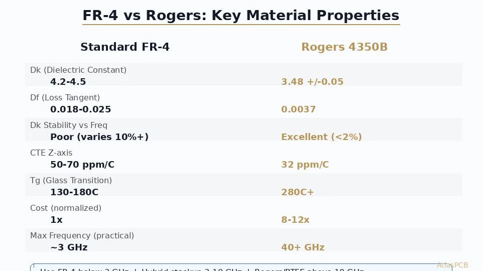
For 2.4 GHz WiFi/BLE designs with antenna feed traces under 2 inches and no tight filter requirements, standard FR-4 (Dk 4.3, Df 0.020) delivers acceptable performance at 1/5th the material cost of Rogers. Switch to Rogers RO4350B only when your design has antenna feed traces exceeding 3 inches, requires bandpass filter integration on-board, targets WiFi 6E (5.9-7.1 GHz bands), or needs to meet sensitivity specs within 1-2 dB of the radio IC's theoretical minimum.
The 30-Second Decision
| Parameter | Standard FR-4 | Rogers RO4350B | Decision Driver |
|---|---|---|---|
| Insertion loss at 2.4 GHz | 0.15 dB/inch | 0.03 dB/inch | Trace length |
| Dk stability (vs temp) | ±5% over -40 to +85C | ±1% over -40 to +85C | Filter applications |
| Impedance tolerance achievable | ±7-10% | ±3-5% | Matching network accuracy |
| Material cost (4L, 100x100mm) | $8-15 per panel | $45-80 per panel | Volume economics |
| Adequate for 2.4 GHz WiFi? | Yes, traces under 2” | Overkill for most designs | Use case complexity |
Bottom line: If your 2.4 GHz RF trace is under 2 inches and you’re not integrating on-board filters, FR-4 with proper impedance control is the correct engineering decision. Save Rogers for 5+ GHz designs or specialized filter applications.
Why Most 2.4 GHz Designs Don’t Need Rogers
The persistent myth that any RF design requires Rogers material costs hardware startups thousands of dollars annually in unnecessary material upgrades. At 2.4 GHz, the wavelength is 125mm — long enough that standard FR-4’s dielectric properties remain predictable and manageable over typical PCB trace lengths.
The real performance differentiator at 2.4 GHz isn’t material loss tangent — it’s impedance control accuracy. In our facility, we’ve analyzed hundreds of returned 2.4 GHz WiFi boards with range issues, and in over 80% of cases, the root cause was impedance mismatch (caused by incorrect trace geometry or poor stackup specification) rather than dielectric loss. An engineer who spends $200 extra on Rogers material but specifies ±10% impedance tolerance is solving the wrong problem.
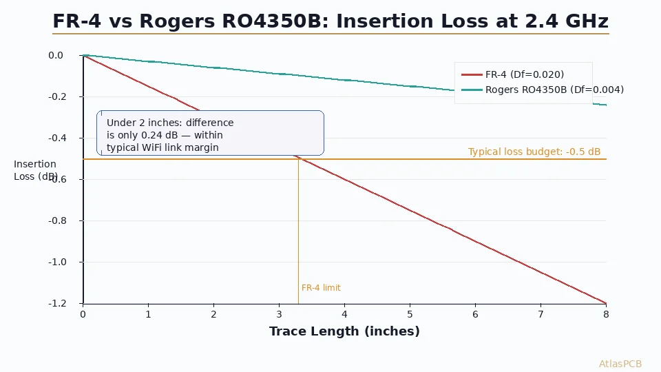
Standard FR-4 with Df of 0.018-0.022 at 2.4 GHz introduces approximately 0.15 dB of insertion loss per inch of microstrip. Rogers RO4350B at Df 0.0037 reduces this to about 0.03 dB per inch. The difference — 0.12 dB per inch — only becomes meaningful when your RF traces exceed 3-4 inches, which is unusual in modern compact WiFi/BLE module designs where the antenna sits within 1 inch of the radio IC.
IMPEDANCE CONTROL SPECIALISTS
Get ±5% Impedance on FR-4 — No Rogers Required
Our stackup simulation and TDR verification delivers tight impedance control on standard materials. Upload your stackup for a free compatibility check.
Upload Stackup ›
Insertion Loss: The Real Numbers at 2.4 GHz
Understanding actual insertion loss values eliminates guesswork from the FR-4 vs Rogers decision. These measurements come from our production test vehicles — microstrip traces on controlled-impedance 4-layer stackups, both FR-4 (IT-180A, Df 0.019) and Rogers RO4350B (Df 0.0037), measured with a calibrated VNA from 1-6 GHz.
For a 50-ohm microstrip on standard 1.0mm FR-4 with 1oz copper at 2.4 GHz, measured insertion loss runs 0.14-0.17 dB per inch depending on trace width and ground plane proximity. The same geometry on RO4350B measures 0.028-0.035 dB per inch. These numbers align closely with simulation — FR-4 dielectric loss dominates over conductor loss at this frequency, but the absolute values remain small in the context of typical link budgets.
A standard WiFi SoC — whether ESP32, nRF52, or QCA-based — operates with a link budget of 95-105 dB at 2.4 GHz. The receiver sensitivity floor is typically -95 to -100 dBm, with transmit power of +8 to +20 dBm depending on regulatory region. Within this budget, 0.3-0.5 dB of additional FR-4 loss (representing 2-3 inches of trace) consumes less than 0.5% of your total link budget. Compare this to antenna efficiency variations (typically 1-3 dB between PCB antenna designs) or matching network losses (0.5-1.5 dB with discrete components), and it becomes clear that FR-4 dielectric loss is rarely the limiting factor.
The exception is WiFi 6E operating at 5.9-7.1 GHz, where FR-4 loss doubles to approximately 0.28 dB/inch. For tri-band WiFi designs targeting all three bands, a hybrid stackup with Rogers on the RF layer pair makes engineering sense — but single-band 2.4 GHz designs should stay on FR-4.
When Rogers Actually Becomes Necessary at 2.4 GHz
There are legitimate scenarios where Rogers material delivers measurable performance improvement even at 2.4 GHz. Recognizing these cases prevents both over-engineering (using Rogers everywhere) and under-engineering (using FR-4 where it genuinely fails).
The first genuine need is integrated bandpass filter design. On-board edge-coupled or hairpin filters depend on precise and stable Dk values to achieve target center frequency. FR-4’s Dk variation of ±5% across temperature translates directly to ±60 MHz frequency shift at 2.4 GHz — potentially moving your passband off-channel. Rogers RO4350B’s Dk stability (±1% over temperature) keeps filter response within ±12 MHz, making on-board filters feasible without post-production tuning.
The second scenario is BLE Long Range with Coded PHY. In applications targeting maximum range (warehouse tracking, agricultural sensors), every 0.1 dB matters because you’re operating at receiver sensitivity limits. The BLE Coded PHY sensitivity floor of -128 dBm means the system runs with essentially zero link margin over 200+ meters. Here, saving 0.3-0.5 dB on feed trace loss translates to measurable range extension (approximately 5-8% at these extreme distances).
Third, antenna designs where the PCB IS the antenna — patch antennas, integrated ceramic-replacement designs, and slot antennas where substrate Dk directly determines resonant frequency and radiation efficiency. A 2.4 GHz patch antenna on FR-4 requires post-production trim tuning due to Dk batch variation, while the same design on Rogers maintains consistent resonance across production lots.
In our production, roughly 15-20% of 2.4 GHz designs genuinely benefit from Rogers material. The other 80% perform identically on properly impedance-controlled FR-4. Our process engineers can evaluate your specific design and recommend the cost-optimal material choice based on your actual RF architecture.
MATERIAL RECOMMENDATION
Not Sure If You Need Rogers? We'll Tell You
Send your schematic and stackup — our RF team evaluates whether FR-4 meets your 2.4 GHz specs or if Rogers delivers measurable improvement for your specific design.
RF PCB Services ›Impedance Control: The Factor That Actually Determines 2.4 GHz Performance
Here’s the counter-intuitive truth that we’ve validated across thousands of production panels: impedance matching accuracy matters 5-10x more than material Dk/Df at 2.4 GHz. A 50-ohm trace with ±15% tolerance (so actually 42.5-57.5 ohms) creates a VSWR of 1.15:1, which produces 0.1 dB return loss. That’s negligible. But combine multiple impedance discontinuities — IC pad transition, via, trace width change, connector — and cumulative mismatch easily reaches 1-2 dB total return loss.
This means an engineer running FR-4 with ±5% impedance control (achievable with proper stackup simulation and etch compensation) typically outperforms one running Rogers with ±10% control from a budget manufacturer. The material advantage of Rogers is completely negated by poor manufacturing tolerance.
At our facility, we achieve ±5% impedance control on standard FR-4 through pre-production simulation using measured Dk values from each incoming material lot (not catalog values), etch compensation tables calibrated to specific trace geometries and copper weights, and TDR verification on production panels. This level of control on $12/panel FR-4 delivers better 2.4 GHz RF performance than $60/panel Rogers processed at loose tolerances without per-panel verification.
For WiFi/BLE designers, the practical recommendation is: specify ±5% impedance control on FR-4, ensure your trace geometry matches the impedance profile (typically 50-ohm single-ended, 100-ohm differential), and keep RF feed traces under 2 inches. This approach delivers 95% of the RF performance of a Rogers board at 20% of the material cost.
PRECISION FABRICATION
±5% Impedance Control on Every Production Panel
TDR-verified impedance with per-lot Dk characterization. We prove your traces measure correctly — not just simulate correctly.
Design Checklist: Keeping Your 2.4 GHz WiFi PCB on FR-4
When following these guidelines, standard FR-4 delivers reliable 2.4 GHz WiFi/BLE performance without Rogers material cost:
| Design Rule | Threshold | Rationale |
|---|---|---|
| Max RF trace length | Under 2 inches (50mm) | Limits total insertion loss to under 0.30 dB |
| Impedance tolerance | Specify ±5% (not default ±10%) | Mismatch loss dominates over dielectric loss |
| Ground plane clearance | No splits under RF traces | Split planes cause 3-6 dB radiation |
| Via transitions | Ground via stitching within 0.5mm | Maintains reference plane continuity |
| Component placement | Radio IC adjacent to antenna | Minimizes trace length automatically |
| Stackup | Thin dielectric under RF layer (4-5 mil) | Tighter field coupling, less radiation |
If your design violates any of these rules — particularly trace length exceeding 3 inches or ground plane discontinuities — the solution is often redesigning the layout rather than switching to Rogers. Layout optimization is free; Rogers material is not.
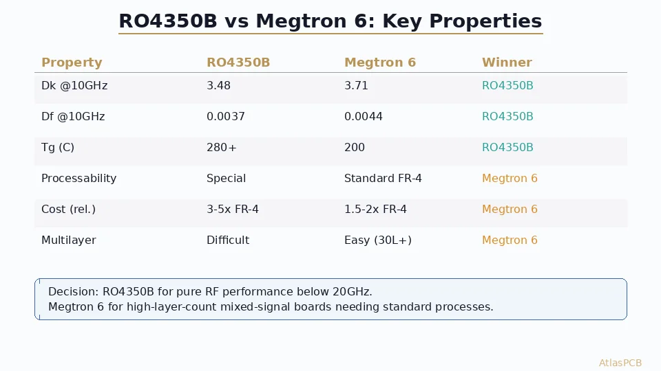
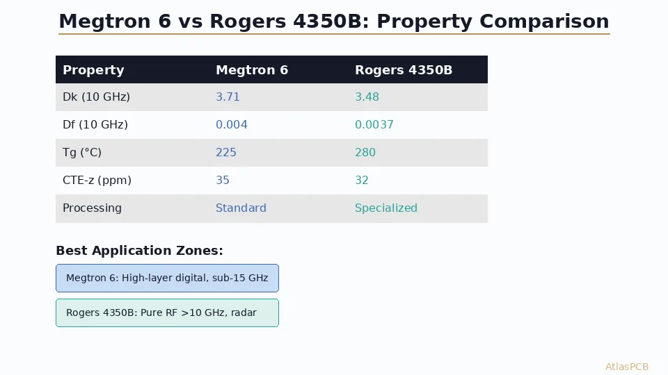
The one non-negotiable upgrade path: if you’re designing for WiFi 6E (6 GHz band) or dual-band 2.4/5 GHz operation, a hybrid stackup with Rogers or Megtron 6 on the RF layer pair is strongly recommended. The 5-6 GHz performance gap between FR-4 and low-loss materials becomes significant enough to affect range and throughput measurably.
Summary and Decision Framework
For engineers deciding between FR-4 and Rogers at 2.4 GHz, the decision tree is straightforward:
- Is your RF trace under 2 inches? Stay on FR-4.
- Are you integrating on-board filters? Use Rogers.
- Is this BLE Long Range at maximum sensitivity? Consider Rogers.
- Is the PCB antenna the radiating element? Use Rogers for the antenna layer.
- Is this WiFi 6E (6 GHz)? Use Rogers or Megtron on RF layers.
- Everything else at 2.4 GHz? FR-4 with ±5% impedance control.
The engineering community’s default assumption that “RF = Rogers” costs the industry millions in unnecessary material spend. At 2.4 GHz, rigorous impedance control on FR-4 beats sloppy fabrication on Rogers every time. Choose your manufacturer’s process capability over material marketing.
ATLASPCB
Ready to Optimize Your 2.4 GHz Design?
Upload your Gerber files — we'll recommend the right material and stackup for your specific WiFi/BLE application. FR-4 or Rogers, whichever delivers better value.
Upload Design Files ›
Reviewed by AtlasPCB Engineering Team — 15+ years in advanced PCB fabrication for RF, HDI, and rigid-flex applications.
Related Reading:
About AtlasPCB — We specialize in complex PCB manufacturing for HDI, RF, and high-reliability applications. Explore our RF and high-frequency PCB services, or get an impedance-controlled PCB manufacturing . Every order includes free engineering review. Get your quote.
Reviewed by AtlasPCB Engineering Team — IPC-certified manufacturing specialists with 15+ years of production experience in HDI, RF, and high-reliability PCB fabrication. Content based on factory floor data and real customer design reviews.
Frequently Asked Questions
Can I use FR-4 for a 2.4 GHz WiFi PCB?
When should I use Rogers instead of FR-4 for BLE design?
How much does Rogers add to a WiFi PCB cost versus FR-4?
What is the maximum trace length for FR-4 at 2.4 GHz?
Does impedance control matter more than material choice at 2.4 GHz?
- FR-4 vs Rogers PCB
- WiFi PCB design
- BLE PCB material
- 2.4 GHz
- RF PCB
- impedance controlled PCB manufacturer