· Marcus Lin · Engineering · 9 min read
FR-4 vs Rogers PCB: When to Switch Materials for RF Designs Above 1 GHz
A practical decision framework for choosing between FR-4 and Rogers laminates. Covers dielectric loss, Dk stability, cost tradeoffs, and the hybrid stackup approach that saves 40% on mixed-signal RF boards.
Quick Answer
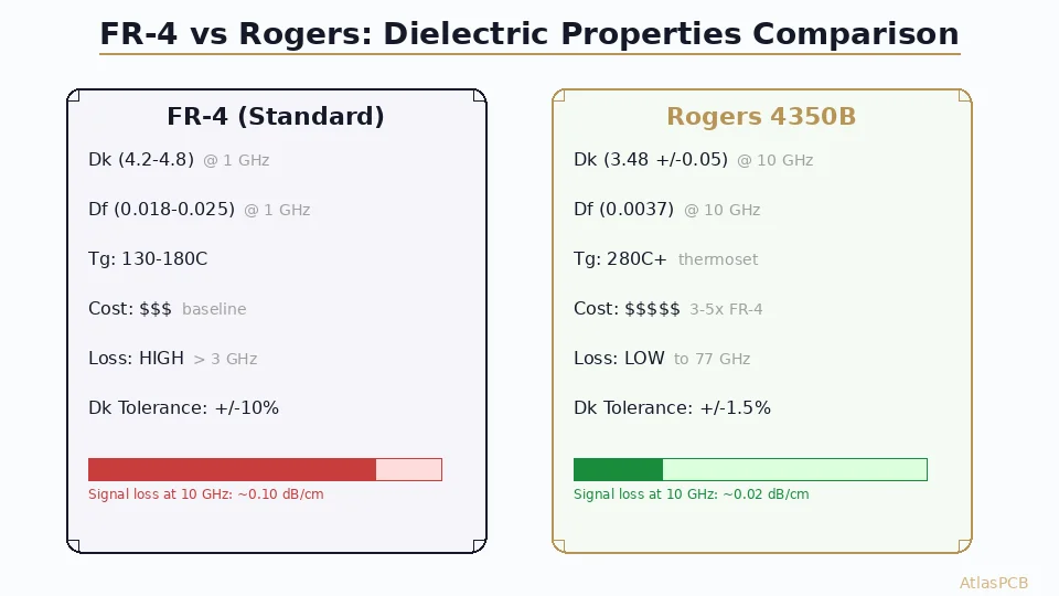
Use FR-4 for digital signals and analog circuits below 1 GHz. Switch to Rogers 4350B or equivalent when operating above 2-3 GHz, when insertion loss budget is tight (less than 0.03 dB/cm), or when Dk tolerance needs to be within +/-2%. For mixed-signal boards, use a hybrid stackup with Rogers on RF layers and FR-4 for digital — this cuts material cost by 40-60% while maintaining RF performance.
30-Second Decision: FR-4 or Rogers?
| Your Application | Frequency | Recommendation | Reason |
|---|---|---|---|
| IoT / BLE / WiFi 2.4 GHz | < 3 GHz | FR-4 (consider hybrid) | Loss budget usually adequate |
| 5G sub-6 (3.5-6 GHz) | 3-6 GHz | Hybrid (Rogers RF + FR-4 digital) | Phase stability needed |
| WiFi 6E / UWB | 6-7 GHz | Rogers (at minimum RF layers) | Dk variation kills matching |
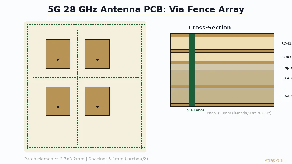
| 5G mmWave / Radar | 24-77 GHz | Full Rogers or PTFE | FR-4 unusable above 10 GHz |
| Digital only (PCIe/DDR) | Baseband | FR-4 (Megtron if 56 Gbps+) | Not an RF problem |
The Real Engineering Tradeoff
The decision between FR-4 and Rogers is fundamentally about loss budget and impedance predictability — not just “higher frequency means better material.” Engineers who default to Rogers for everything waste money, while those who force FR-4 into RF applications waste prototype cycles.
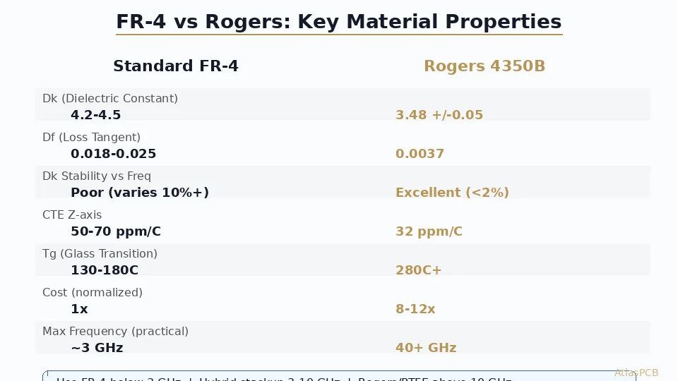
FR-4 is a composite of woven fiberglass and epoxy resin, optimized over decades for mechanical reliability and cost in digital PCBs. Its dielectric constant varies between 4.2 and 4.8 depending on resin content, glass weave style, frequency, and even humidity. At 1 GHz, this variation is manageable because wavelengths are long relative to trace dimensions. At 10 GHz, where a quarter wavelength in FR-4 is approximately 4.5mm, that same +/-10% Dk uncertainty shifts your matching network center frequency by hundreds of MHz.
Rogers RO4350B, by contrast, uses a ceramic-filled hydrocarbon thermoset with tightly controlled filler particle distribution. The result is Dk = 3.48 +/-0.05 from DC to 40 GHz, with a dissipation factor of 0.0037 at 10 GHz. In our production, we consistently measure Dk within +/-0.03 of the datasheet value when we run TDR verification on test coupons — something we do on every RF panel.
Dielectric Loss: The Numbers That Matter
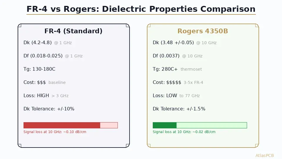
The practical difference shows up most clearly in insertion loss per unit length. In our facility, we routinely measure both materials using TDR and VNA characterization on production panels:
| Property | FR-4 (Std Tg170) | FR-4 (Low-Loss) | Rogers RO4350B | Rogers RO3003 |
|---|---|---|---|---|
| Dk @ 1 GHz | 4.5 | 4.2 | 3.48 | 3.00 |
| Dk @ 10 GHz | 4.2 | 3.9 | 3.48 | 3.00 |
| Df @ 10 GHz | 0.020 | 0.010 | 0.0037 | 0.0013 |
| Loss (dB/cm @ 10 GHz) | 0.10 | 0.06 | 0.025 | 0.012 |
| Dk tolerance | +/-10% | +/-5% | +/-1.5% | +/-1.5% |
| CTE-z (ppm/C) | 50-70 | 45-60 | 32 | 24 |
What this means in practice: a 5cm microstrip trace at 10 GHz loses 0.50 dB in standard FR-4 versus 0.125 dB in RO4350B. For a 77 GHz automotive radar with multiple cascaded filter stages and a corporate feed network, that difference accumulates to the point where FR-4 simply cannot close the link budget.
RF MATERIAL EXPERTISE
Not Sure Which Material Fits Your RF Design?
Our RF engineers review your stackup, simulate loss budgets, and recommend the optimal FR-4/Rogers combination for your frequency band. We stock RO4350B, RO4003C, and hybrid prepregs for fast-turn RF prototypes.
Get Material Recommendation ›
The Hybrid Stackup: Best of Both Worlds
The most cost-effective approach for mixed-signal boards — which describes the vast majority of modern RF products — is a hybrid stackup that places Rogers material only where it is needed. A typical 6-layer hybrid for a 5.8 GHz WiFi module might look like this:
- L1: Rogers RO4350B (6.6mil) — RF signal, patch antenna, matching network
- Prepreg: FR-4 2116 — bonds Rogers core to FR-4 stack
- L2: Copper — ground reference for L1 microstrip
- Core: FR-4 (20mil) — standard digital core
- L3: Copper — power plane
- Prepreg: FR-4 2116
- L4: Copper — digital signals, SPI, I2C, UART
- Core: FR-4 (20mil)
- L5: Copper — ground plane
- Prepreg: FR-4 2116
- L6: Copper — digital signals, power routing
This approach costs roughly 80-100% more than all-FR-4, compared to 200-300% more for all-Rogers. The RF performance on L1 is identical to a pure Rogers board because the signal only interacts with the Rogers dielectric and the L2 ground reference.
The critical manufacturing challenge in hybrid stackups is CTE mismatch at the Rogers/FR-4 boundary during thermal cycling. In our process, we address this with controlled lamination pressure profiles and symmetric stackup construction that balances stress. We have processed over 2,000 hybrid panels in the past year with a registration accuracy of +/-2mil at the material boundary — well within IPC-6012 Class 3 requirements.
Where FR-4 Actually Fails (Real Production Data)
Based on panels we have run across 500+ RF orders this year, the failure modes that push engineers from FR-4 to Rogers cluster around three issues:
Phase inconsistency across production lots. A 5.8 GHz bandpass filter designed on FR-4 with Dk=4.3 shipped 200 boards. The first lot measured center frequency at 5.78 GHz. The third lot, using a different FR-4 supplier’s material with Dk=4.5, shifted to 5.62 GHz. The customer’s receiver frontend could not tolerate this 160 MHz shift. Rogers eliminates this problem because Dk stays within +/-0.05 regardless of supplier lot.
Insertion loss at temperature extremes. FR-4’s dissipation factor increases significantly above 100C. For automotive radar modules that see 125C junction temperatures, the additional loss margin consumed by FR-4’s thermal Df increase often violates the system link budget with no margin for manufacturing variation.
Impedance control precision. We routinely achieve +/-5% impedance tolerance on FR-4 and +/-3% on Rogers. But the absolute predictability matters more than tolerance band — when you simulate a 50-ohm microstrip in your EDA tool, the manufactured board measures 50.2 ohms on Rogers versus 47-53 ohms on FR-4. If your matching network was designed with 0.5 dB return loss margin, that FR-4 variation eats your entire budget.
CHINA RF PCB MANUFACTURER
Rogers RF Boards with TDR Verification on Every Panel
We maintain Rogers RO4350B and RO4003C inventory for 5-day RF prototype turns. Every impedance-controlled RF board ships with a TDR test report showing measured vs. target impedance on production coupons.
View RF Capabilities ›Process Compatibility: Why RO4350B Wins for Most Hybrid Designs
Not all Rogers materials behave the same in manufacturing. RO4350B was engineered specifically for compatibility with standard FR-4 fabrication processes, which is why it dominates the commercial RF market. PTFE-based materials like RO5880 offer lower loss (Df=0.0009) but require completely different drilling parameters, cannot use standard oxide surface treatments for bonding, and need specialized sodium etchant preparation.
In our facility, we process RO4350B with the same drill bits, speeds, and feeds as FR-4. The same solder mask, same plating chemistry, same press cycle (with adjusted temperature profile). This means a hybrid FR-4/RO4350B board runs through our line without special tooling — keeping lead times at 5-7 days for prototypes versus 10-14 days for PTFE-based designs that require separate process routing.
For applications above 40 GHz where RO4350B’s 0.0037 Df becomes limiting, we typically recommend RO3003 or RO3006 (ceramic-filled PTFE) which offers Df=0.0013 at 10 GHz. These materials require modified processing but deliver performance up to 77 GHz automotive radar frequencies.
Decision Framework: Frequency vs. Cost Sensitivity
The right choice depends on three variables: operating frequency, loss budget tightness, and production volume. Here is how we guide customers through this decision:
Use FR-4 when: Your highest frequency signal is below 1 GHz, OR you are building a prototype with generous loss margins to validate functionality before committing to Rogers for production. Standard FR-4 costs $15-30 per panel (100x100mm, 4-layer). Total board cost for 10 prototypes: $150-300.
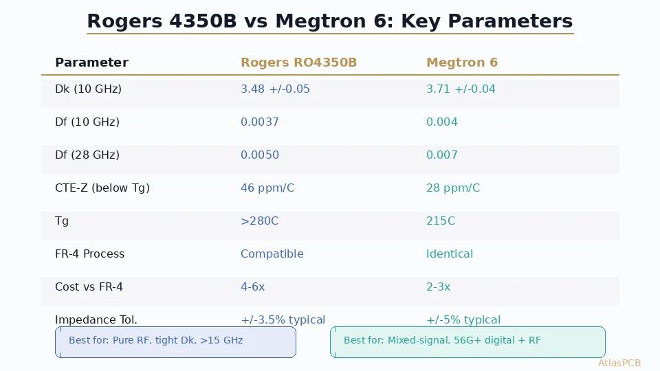
Use low-loss FR-4 (Megtron 6, Panasonic R5775K) when: Operating between 3-10 GHz with moderate loss requirements, or running high-speed digital (56 Gbps PAM4 SerDes) where PTFE process complexity is not justified. Cost premium: 1.5-2x standard FR-4.
Use Rogers RO4350B (hybrid) when: RF sections operate at 2-40 GHz, you need Dk predictability for filter/matching design, and your board has both RF and digital sections. This is the sweet spot for WiFi 6E, 5G sub-6, and C-band SATCOM. Cost premium: 2-3x for the hybrid vs. all-FR-4.
Use Rogers RO3003/PTFE when: Operating above 40 GHz (77 GHz radar, 60 GHz WiGig, E-band backhaul). Loss is the dominant constraint. Be prepared for longer lead times and 4-5x material cost.
HYBRID STACKUP DESIGN
Upload Your Design for a Free Stackup Review
Send us your Gerbers and frequency requirements. Our process engineers will recommend the optimal material combination and provide a detailed impedance simulation report with your quote.
Summary: The Practical Crossover
The industry has largely converged on this reality: below 1 GHz, FR-4 is always sufficient. Between 1-3 GHz, it depends on your tolerance stack and loss margin. Above 3 GHz, Rogers (or equivalent ceramic-filled hydrocarbon) on at least the RF signal layers is the professional choice for production designs.
The hybrid stackup approach represents the best value proposition for the majority of modern wireless products. It delivers Rogers-grade RF performance where needed while keeping digital layer costs at FR-4 levels. The manufacturing complexity is minimal when your fabricator has established hybrid press profiles — which is exactly what we maintain for our RF customers.
ATLASPCB
Ready to Finalize Your RF Material Selection?
Get an instant quote with Rogers material options. We stock RO4350B and RO4003C for fast-turn prototypes, and our engineering team reviews every RF stackup before production.
Get Instant Quote ›
Reviewed by AtlasPCB Engineering Team — 15+ years in advanced PCB fabrication for RF, HDI, and rigid-flex applications.
Related Reading:
About AtlasPCB — We specialize in complex PCB manufacturing for HDI, RF, and high-reliability applications. Explore our RF and high-frequency PCB services . Every order includes free engineering review. Get your quote.
Reviewed by AtlasPCB Engineering Team — IPC-certified manufacturing specialists with 15+ years of production experience in HDI, RF, and high-reliability PCB fabrication. Content based on factory floor data and real customer design reviews.
Frequently Asked Questions
At what frequency should I switch from FR-4 to Rogers?
Can I use a hybrid stackup with both FR-4 and Rogers?
How much more does Rogers cost compared to FR-4?
Is Rogers 4350B compatible with standard FR-4 fabrication processes?
What Dk tolerance can I expect from FR-4 vs Rogers?
- FR-4 vs Rogers PCB
- Rogers 4350B
- RF PCB material
- China RF PCB manufacturer
- PCB material selection