· David Okafor · Engineering · 9 min read
EV Battery Management System PCB
Building PCBs for 800V EV battery management systems requires specific material selections, creepage compliance, and manufacturing processes that most fabricators cannot deliver reliably. This guide covers the PCB specifications, rigid-flex design constraints, and manufacturing parameters for automotive-grade BMS boards.
Quick Answer
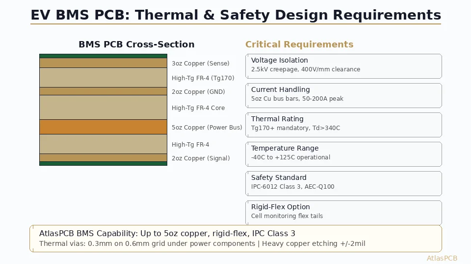
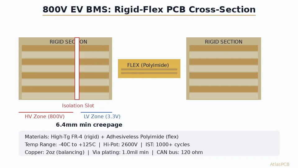
800V EV BMS PCBs require minimum 6.4mm creepage/clearance between high-voltage and low-voltage zones (per IEC 60664-1 at Pollution Degree 2), high-Tg FR-4 or polyimide substrate rated for -40C to +125C continuous operation, minimum 2oz copper on current-sensing layers, and controlled impedance on CAN/LIN bus communication traces. Rigid-flex construction is increasingly mandated to replace harness connections between cell monitoring ICs distributed across the battery pack.
The 800V Transition Changes PCB Requirements Fundamentally
The automotive industry’s shift from 400V to 800V battery architectures is not merely a voltage doubling exercise for PCB designers. It fundamentally changes the creepage geometry, material requirements, and testing protocols for every board in the battery management system. What worked at 400V — where 3.2mm creepage was adequate and standard FR-4 sufficed — becomes non-compliant and potentially dangerous at 800V.
From our experience fabricating BMS boards for Tier 1 automotive suppliers, the 800V transition has exposed three categories of problems that did not exist at 400V: boards that pass electrical test but fail Hi-Pot at incoming inspection, rigid-flex assemblies that survive initial qualification but develop flex-zone cracks under thermal cycling, and communication bus impedance drift as substrate Dk shifts across the -40C to +125C operating range.
Creepage and Clearance: The Geometry That Drives Board Size
The most immediate design impact of 800V architecture is the physical space required for voltage isolation. Per IEC 60664-1 at Pollution Degree 2 (the classification for sealed automotive enclosures):
| Working Voltage | Minimum Creepage | Minimum Clearance | Practical Board Impact |
|---|---|---|---|
| 400V DC | 3.2 mm | 3.0 mm | Manageable with standard routing |
| 800V DC | 6.4 mm | 5.5 mm | Requires dedicated isolation zones |
| 800V DC (with OEM margin) | 8.0 mm | 6.5 mm | Significant board area consumed |
These distances must be maintained between any high-voltage trace or component and any low-voltage circuit on the same board. For a BMS front-end IC (like the ADBMS6830 or MAX17853) that bridges between the cell stack voltage domain and the isolated communication interface, this means 6.4-8mm of empty board space — with no copper, no vias, and no silkscreen — separating the two domains.
On a typical 12S cell monitoring board measuring 60x40mm, the isolation zone consumes approximately 15-20% of total board area at 800V versus only 8-10% at 400V. This is real estate that cannot be used for routing, requiring either larger boards or higher-density routing in the remaining space.
Slot and Cutout Strategies
Many BMS designs use routed slots (milled channels through the PCB) at the isolation boundary. A slot breaks the surface creepage path, allowing the same physical distance to achieve higher effective creepage. A 2mm-wide slot can reduce the required board-surface creepage distance because the creepage path must follow the slot contour rather than crossing it directly.
However, slots introduce manufacturing constraints: minimum slot width is typically 1.0mm (routing bit diameter), and the slot edges must maintain 0.5mm clearance to any copper on adjacent layers. In multilayer BMS boards, the slot must extend through all layers — including internal planes — requiring careful power plane design to avoid interrupting return current paths.
AUTOMOTIVE PCB EXPERTISE
800V BMS PCB Fabrication with Full Creepage Compliance
We fabricate BMS rigid-flex boards for Tier 1 automotive suppliers with verified Hi-Pot testing, IPC Class 3/A workmanship, and full creepage/clearance documentation per IEC 60664-1.
Discuss Your BMS PCB Requirements ›
Rigid-Flex Construction for Distributed BMS
Modern EV battery packs distribute cell monitoring across multiple modules. A typical 400V pack has 96 cells in 8 modules of 12; an 800V pack doubles to 192 cells across 16 modules. Each module requires a local cell monitoring board connected to a central BMS controller.
The traditional approach — individual rigid PCBs connected by wire harnesses — creates reliability problems in the automotive vibration environment. Every connector is a potential failure point, and harness routing in the confined space of a battery pack adds assembly time and cost.
Rigid-flex BMS boards solve this by integrating the inter-module connections into the PCB structure itself. The rigid sections house the cell monitoring ICs and passive components, while flex sections bridge between modules. This eliminates connectors entirely for the intra-pack communication bus.
Manufacturing Challenges Specific to BMS Rigid-Flex
Flex bend radius at voltage: The flex sections in an 800V BMS must maintain creepage isolation while bent to final installed radius. If high-voltage and low-voltage traces are present in the same flex section (which they sometimes must be for cell tap connections), the bent geometry can reduce effective clearance below specification. Our process engineering team calculates effective clearance at installed bend radius — not flat — to ensure compliance.
Polyimide vs adhesive selection: Standard acrylic adhesive for flex layers is rated to +85C continuous — insufficient for automotive BMS. Modified epoxy or adhesiveless polyimide constructions are mandatory for the +125C requirement. Adhesiveless polyimide (where the copper is directly deposited on PI film) costs 40-60% more but eliminates the weakest thermal link in the flex stack.
Via reliability through thermal cycling: Automotive BMS boards endure -40C to +125C thermal cycling — a 165C delta that stresses via barrel plating severely. Standard electroless copper at 0.8mil thickness fails at 500-800 cycles. Automotive BMS requires minimum 1.0mil copper plating thickness with elongation >18% verified by IST coupon testing.
RIGID-FLEX SPECIALIST
Automotive-Grade Rigid-Flex PCB Manufacturing
Up to 22-layer rigid-flex with adhesiveless polyimide, IST-verified via reliability, and IATF 16949-aligned quality systems. From prototype through production volume.
Material Selection for 800V BMS PCBs
Rigid Sections
| Requirement | Material Solution | Why |
|---|---|---|
| -40C to +125C continuous | High-Tg FR-4 (Tg170+) minimum | Tg150 loses mechanical properties above 130C |
| CTI > 400 for HV zones | Specific laminate grades (Shengyi S1141, ITEQ IT-170GRA) | Standard FR-4 CTI varies; must be specified |
| Halogen-free (EU OEM requirement) | Green chemistry laminates | RoHS + additional EU automotive directives |
| CAN bus impedance stability | Controlled-Dk material for comm layers | Dk must be stable across -40C to +125C range |
Flex Sections
| Requirement | Material Solution | Why |
|---|---|---|
| +125C continuous operation | Adhesiveless polyimide (PI) | Acrylic adhesive fails above 85C |
| 1M+ bend cycles (vibration) | 1oz RA (rolled annealed) copper | ED copper grain structure cracks under repeated flex |
| Thin overall thickness | 12.5μm or 25μm PI base | Must fit within battery pack flex routing space |
Copper Weight Considerations
Cell voltage sensing traces carry negligible current (μA-level ADC inputs) and can use standard 0.5oz copper. However, cell balancing discharge paths may carry 100-300mA continuously, and temperature sensing analog front-ends benefit from wider, heavier traces for thermal noise reduction.
The current-carrying requirement typically drives 2oz copper on at least one layer for the balancing resistor connections. In passive balancing designs dissipating 50-200mW per cell, the PCB copper itself contributes to heat spreading — making 2oz copper a thermal requirement as much as an electrical one.
Communication Bus Impedance Control
Every modern BMS uses isolated communication between cell monitoring ICs and the central controller — typically isoSPI (Analog Devices), UART with digital isolator (TI/Maxim), or CAN bus. These communication traces require impedance control to ensure reliable data transfer, particularly as trace lengths increase in distributed rigid-flex designs.
| Bus Type | Impedance Target | Tolerance Required | Typical Trace Length |
|---|---|---|---|
| isoSPI (differential) | 100Ω differential | ±10% | 50-300mm |
| CAN bus (differential) | 120Ω differential | ±10% | 100-2000mm |
| SPI (single-ended, isolated) | 50Ω single-ended | ±10% | 20-100mm |
For rigid-flex BMS boards, maintaining impedance through the rigid-to-flex transition is the critical challenge. The dielectric thickness and material (FR-4 in rigid vs PI in flex) change at the transition, requiring trace width adjustment at the boundary to maintain constant impedance. In our fabrication process, we model the transition zone geometry to verify impedance continuity — not just the individual rigid and flex sections independently.
IMPEDANCE CONTROLLED
Controlled Impedance Through Rigid-Flex Transitions
We model impedance continuity across rigid-to-flex boundaries with TDR verification on production panels. Standard ±10% tolerance; ±5% available for critical communication buses.
View Impedance Capabilities ›Testing and Qualification Requirements
Automotive BMS PCBs undergo testing that standard commercial boards never see:
Hi-Pot testing: Every production board tested at 2x working voltage + 1000V between HV and LV zones. For 800V systems: 2600V applied for 60 seconds. Any leakage above 10μA is a reject. This catches manufacturing defects that electrical continuity testing misses — resin voids near isolation slots, copper splash near creepage boundaries, and contamination bridging isolation gaps.
Thermal cycling: IPC-TM-650 Method 2.6.7.2 — minimum 1000 cycles at -40C to +125C with 10-minute dwell at each extreme. Via failures typically manifest between 500-1500 cycles depending on plating quality and aspect ratio. We destructively test IST coupons from every production lot to verify barrel integrity.
Ionic contamination: IPC-TM-650 Method 2.3.25 — maximum 1.56 μg/cm² NaCl equivalent on delivered boards. In high-voltage BMS applications, ionic residues create leakage paths that compromise isolation over time. Our cleaning process achieves consistently below 0.8 μg/cm² with verification on every production lot.
Cross-section analysis: Microsection verification of copper plating thickness (minimum 1.0mil barrel, 0.8mil hole wall), dielectric thickness at impedance-controlled layers, and flex layer adhesion quality. Performed on first-article and periodic production sampling.
Cost Considerations for 800V BMS Rigid-Flex
An automotive-grade 800V BMS rigid-flex board is among the most expensive PCBs in any vehicle. Typical cost drivers versus a standard rigid board of equivalent area:
| Cost Factor | Multiplier vs Standard Rigid | Reason |
|---|---|---|
| Rigid-flex construction | 3-5x | Multiple lamination cycles, flex material, alignment |
| Automotive material spec | 1.3-1.5x | High-Tg, CTI-rated, halogen-free laminate |
| 2oz copper (selected layers) | 1.2-1.3x | Longer etch time, wider minimum trace |
| Hi-Pot testing (100%) | 1.1-1.2x | Dedicated test fixture, longer test time per board |
| IST/thermal cycling qualification | Fixed NRE | $3000-8000 per design qualification |
| Documentation package (PPAP) | Fixed NRE | $2000-5000 for full PPAP submission |
For a typical 8-layer rigid-flex BMS monitoring board (100x60mm rigid, two 150mm flex tails), expect prototype pricing of $400-800 per board (5 pieces) and production pricing of $35-65 per board (10,000 pieces). The steep volume curve reflects high fixed costs in tooling, test fixture development, and qualification that amortize across production volume.
ATLASPCB
Ready to Build Your 800V BMS PCB?
From rigid-flex prototype through automotive production. We provide full DFM review, material recommendation, creepage verification, and Hi-Pot tested delivered boards. Up to 22-layer rigid-flex with IST-verified reliability.
Get BMS PCB Quote ›
Reviewed by AtlasPCB Engineering Team — 15+ years in advanced PCB fabrication for RF, HDI, and rigid-flex applications.
Related Reading:
About AtlasPCB — We specialize in complex PCB manufacturing for HDI, RF, and high-reliability applications. Explore our rigid-flex PCB manufacturing, or get an impedance-controlled PCB manufacturing . Every order includes free engineering review. Get your quote.
Reviewed by AtlasPCB Engineering Team — IPC-certified manufacturing specialists with 15+ years of production experience in HDI, RF, and high-reliability PCB fabrication. Content based on factory floor data and real customer design reviews.
Frequently Asked Questions
Why do 800V BMS PCBs need rigid-flex construction?
What creepage distance is required for 800V BMS PCBs?
What PCB material is required for EV BMS boards?
Can a standard PCB manufacturer build 800V BMS boards?
What testing is required for automotive BMS PCBs?
- rigid-flex PCB manufacturer
- PCB manufacturer for aerospace
- impedance controlled PCB manufacturer
- EV BMS
- automotive PCB