· Sophia Reyes · Engineering · 10 min read
Impedance Controlled PCB Cost
A transparent breakdown of impedance controlled PCB pricing — why it costs 15-40% more than standard boards, which design decisions drive the premium, and practical optimization strategies that maintain signal integrity while cutting manufacturing cost.
Quick Answer
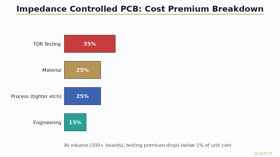
Impedance controlled PCBs cost 15-40% more than equivalent standard boards, driven primarily by TDR testing (coupon fabrication + measurement), tighter etching tolerances (slower process = lower throughput), and constrained material selection (specific Dk laminates in specific thicknesses). The biggest cost lever is consolidating impedance requirements: fewer unique impedance targets per board means fewer test coupons and simpler stackup optimization. A board with 3 impedance targets costs roughly 20% less to verify than one with 8 targets.
Impedance Controlled PCB Cost: The Numbers Upfront
| Board Type | Layers | Impedance Targets | Tolerance | Typical Premium |
|---|---|---|---|---|
| USB/PCIe digital | 4-6 | 2-3 (50, 90, 100 ohm) | +/-10% | 15-20% |
| High-speed networking | 8-12 | 4-6 (varied SE + diff) | +/-10% | 20-30% |
| RF/mixed signal | 6-10 | 3-5 (varied + RF) | +/-5% on RF | 30-40% |
| Server/HPC | 16-24 | 6-8+ (multi-rate SerDes) | +/-7% | 25-35% |
| Simple impedance (50 ohm only) | 4 | 1 | +/-10% | 10-15% |
These premiums are over an identical layer-count board without impedance control. The premium covers material constraints, process modifications, and testing infrastructure — not simply a manufacturer markup.
What Actually Costs Money: The Four Premium Drivers
Understanding where the impedance premium comes from helps you make informed design decisions that optimize cost without sacrificing performance.
The first and most visible cost driver is TDR verification testing. Every impedance-controlled panel set requires test coupons — dedicated trace structures built into the panel border that replicate the impedance geometries on your board. Our process fabricates 4-6 coupon sets per panel (depending on the number of unique impedance targets), and each coupon undergoes time-domain reflectometry measurement after fabrication. The TDR equipment, coupon design, measurement, and documentation costs approximately $80-150 per panel set regardless of how many boards that panel contains. On a prototype panel containing 5 boards, that is $16-30 per board. On a production panel containing 100 boards, it is $0.80-1.50 per board. This fixed-cost nature makes impedance control proportionally expensive at prototype quantities and nearly free at volume.
The second cost driver is constrained material selection. When you specify impedance targets, the manufacturer cannot freely choose whatever laminate is cheapest or most available — the stackup must use specific dielectric thicknesses and specific Dk values to hit your impedance numbers. A standard board might use whatever 4mil prepreg is on the shelf; an impedance-controlled board needs 4mil 1080 glass style (Dk 4.15) specifically, because 4mil 2116 glass style (Dk 4.25) would push the impedance off-target. This constraint means the manufacturer sometimes pays a premium for specific material SKUs, or carries more inventory to support impedance work. The material premium typically adds 5-10% to the board cost.
Third, the etching process runs tighter. Impedance is determined by trace width (among other factors), so the etch process must hold trace width within +/-0.5mil for +/-5% impedance tolerance, compared to +/-1mil for standard non-impedance boards. Achieving this tighter etch tolerance requires slower conveyor speed through the etcher, more frequent solution monitoring, and lower panel density per etch cycle — all reducing throughput. The process premium is approximately 8-15% of fabrication cost.
Fourth, impedance-controlled boards require additional engineering time during CAM preparation. An engineer must calculate expected impedance for each target using the actual laminates selected, design the test coupons, and create the impedance test specification. This front-end engineering adds 1-2 hours per unique design, costing $50-100 that is amortized across the order quantity.
IMPEDANCE CONTROLLED PCB MANUFACTURER
Get a Transparent Impedance PCB Quote
We quote impedance boards with the tolerance, testing, and material costs itemized — no hidden markups. Upload your stackup and impedance table.
Get Instant Quote ›
Tolerance Selection: The Biggest Cost Lever You Control
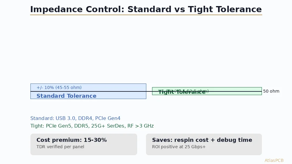
The single design decision with the largest cost impact is your impedance tolerance specification. The difference between +/-10% and +/-5% is not merely 5 percentage points — it cascades through material selection, process parameters, and yield.
At +/-10% tolerance, the manufacturer has flexibility to use standard-thickness laminates with typical Dk variation. If the laminate Dk is 4.2 instead of the nominal 4.35, the resulting impedance shift of approximately 3% stays comfortably within the +/-10% window. Manufacturing yield at +/-10% tolerance typically exceeds 95% on the first pass — meaning less than 5% of panels need process adjustment or scrapping.
At +/-5% tolerance, the Dk variation budget shrinks dramatically. That same 4.2 vs 4.35 Dk shift now consumes more than half the allowable impedance window, leaving almost no margin for trace width variation. The manufacturer must either use premium laminates with tighter Dk specifications (adding 10-15% material cost), or select material lots through incoming QC testing (adding time and scrapping non-conforming lots). First-pass yield at +/-5% drops to 80-85% — meaning 15-20% of panels may need rework or are scrapped.
The practical guidance is: specify +/-10% unless your link budget analysis specifically shows that 10% impedance variation causes bit error rate degradation. Most high-speed protocols (USB 3.2, PCIe Gen4, HDMI 2.1, DDR5) specify board impedance at +/-10% in their compliance specs. PCIe Gen5 and 112G PAM4 lanes benefit from +/-7%, and only precision RF applications (phase-matched antenna feeds, filter banks) genuinely require +/-5%.
When Tight Tolerance Pays for Itself
There are scenarios where specifying +/-5% actually reduces total system cost despite the board premium. If your alternative to tight impedance tolerance is adding equalization hardware (retimers, active cable drivers, or additional SerDes emphasis taps), the BOM cost of those components often exceeds the PCB premium. A single PCIe retimer IC costs $5-15 per board. If tighter PCB impedance eliminates the need for a retimer, the $2-4 impedance premium per board saves money net.
Similarly, in phased-array antenna systems where impedance mismatch between channels creates beam-pointing error, the cost of calibration algorithms and additional test time at system integration can dwarf the PCB premium for tighter impedance matching across all channels.
Material Selection: Designing for Cost Without Sacrificing Performance
The most effective cost optimization is designing your impedance targets around standard available dielectric thicknesses rather than specifying arbitrary target impedances and expecting the manufacturer to find matching materials.
Standard prepreg thicknesses available from all major laminate suppliers (Isola, Shengyi, ITEQ) include 2.7mil (1080 single ply), 3.5mil (1080 double ply), 4.5mil (2116 single ply), and 5.8mil (2116 double ply). Custom thicknesses — anything between these standards — require either sourcing specialty prepreg (with 2-4 week lead time and minimum order quantities) or using multiple thin plies to achieve an intermediate thickness (adding cost and layer complexity).
A practical approach: during schematic capture, calculate your impedance requirements using standard dielectric thicknesses and adjust trace width to hit your targets rather than specifying a trace width and asking the manufacturer to match it with custom dielectric. A 50-ohm microstrip on 4.5mil prepreg requires approximately 7.5mil trace width; on 3.5mil prepreg, it requires approximately 5.8mil. Both are manufacturable — choose the dielectric that keeps your trace width in a comfortable range for your routing density.
This approach — designing trace width to fit standard materials — saves 15-20% versus the alternative of constraining materials to fit an arbitrary trace width. Most experienced layout engineers use 2-3 standard prepreg thicknesses and adjust trace widths accordingly.
STACKUP OPTIMIZATION
We Design Impedance Stackups for Your Budget
Send your impedance targets and we will return an optimized stackup using standard materials — with trace widths pre-calculated and verified against our actual laminate stock.
Request Stackup Design ›Consolidating Impedance Targets: Fewer Targets = Lower Cost
Every unique impedance target on your board requires a separate test coupon, a separate TDR measurement, and a separate process verification. A board with 8 impedance targets (50, 55, 75, 85, 90, 95, 100, 120 ohm) requires 8 coupon structures, 8 measurement cycles, and 8 pass/fail criteria — roughly doubling the testing cost versus a 3-target board.
The consolidation strategy is straightforward: examine whether any targets can be merged. In many designs, engineers specify 50 ohm for single-ended and 100 ohm differential as separate targets — but 100 ohm differential is simply two 50-ohm traces with controlled coupling, meaning the same stackup layer and trace geometry serves both. They can often share a single coupon set.
Similarly, if your design has 85 ohm and 90 ohm targets on the same layer, check whether both can be routed at 90 ohm. Most protocols that specify 85 ohm (older USB) actually have a +/-10% tolerance window that includes 90 ohm. Consolidating these into one target eliminates a coupon set.
In our experience across approximately 500 impedance-controlled orders per quarter, the average design specifies 4.2 unique impedance targets. After discussion with the designer, approximately 60% of these can be reduced by 1-2 targets through consolidation, saving $30-80 per panel set in testing cost. On prototype runs, this consolidation can reduce the per-board impedance premium by 15-25%.
Volume Pricing: How Impedance Cost Scales
The impedance premium follows a non-linear cost curve that favors volume orders:
| Quantity | Testing Cost/Board | Material Premium/Board | Process Premium/Board | Total Premium |
|---|---|---|---|---|
| 5 boards (proto) | $16-30 | $2-4 | $3-5 | $21-39 (30-50%) |
| 50 boards | $2-3 | $2-4 | $2-4 | $6-11 (20-30%) |
| 500 boards | $0.20-0.30 | $1.5-3 | $1.5-3 | $3.20-6.30 (12-18%) |
| 5000 boards | $0.02-0.03 | $1-2 | $1-2 | $2-4 (8-12%) |
At volume production (5000+ boards), the impedance premium converges toward 8-12% — almost entirely driven by material and process constraints, with testing cost becoming negligible. This is why production designs should not compromise signal integrity to save the impedance premium — at volume, it costs very little.
The cost breakpoint where impedance control becomes “essentially free” (under 10% premium) varies by board complexity, but for most 6-8 layer designs, it occurs around 200-500 boards per order.
VOLUME PRICING
Production Impedance Boards from $0.08/cm2
At production quantities, impedance control adds minimal per-unit cost. Get volume pricing for your next production run.
Get Volume Quote ›Common Pricing Mistakes to Avoid
Three design practices unnecessarily inflate impedance controlled PCB cost without improving signal performance.
First, specifying impedance on layers that do not carry high-speed signals. If your board has 10 layers but only layers 3 and 7 carry impedance-critical traces, specify impedance control on those 2 layers only. Specifying “all layers impedance controlled” doubles testing cost and constrains material selection across the entire stackup for layers that do not benefit.
Second, using non-standard impedance values without engineering justification. A 57-ohm target (instead of 50 or 55) may require a custom dielectric thickness that no standard prepreg matches, forcing material special-ordering or multi-ply construction. Before committing to unusual impedance values, verify that standard laminate thicknesses can achieve your target with manufacturable trace widths.
Third, neglecting to provide a stackup drawing with impedance specifications. When a manufacturer receives impedance requirements without a stackup, they must design one from scratch — adding engineering time and potentially selecting materials that differ from what the designer assumed during impedance modeling. Always provide your modeled stackup alongside impedance requirements so the manufacturer can verify feasibility and suggest optimizations rather than starting from zero.
ATLASPCB
Ready to Order Impedance Controlled PCBs?
Upload your Gerbers with stackup and impedance table for transparent pricing. TDR-verified, +/-5% or +/-10% tolerance, 5-12 day lead time.
Get Instant Quote ›
Reviewed by AtlasPCB Engineering Team — 15+ years in advanced PCB fabrication for RF, HDI, and rigid-flex applications.
Related Reading:
About AtlasPCB — We specialize in complex PCB manufacturing for HDI, RF, and high-reliability applications. Explore our impedance-controlled PCB manufacturing, instant online PCB quote, or get an full PCB manufacturing capabilities . Every order includes free engineering review. Get your quote.
Reviewed by AtlasPCB Engineering Team — IPC-certified manufacturing specialists with 15+ years of production experience in HDI, RF, and high-reliability PCB fabrication. Content based on factory floor data and real customer design reviews.
Frequently Asked Questions
How much does impedance control add to PCB cost?
What impedance tolerance should I specify — +/-5% or +/-10%?
Does impedance control cost more for prototype vs volume orders?
Can I reduce impedance controlled PCB cost without compromising signal integrity?
Why does my impedance controlled board need test coupons?
- impedance controlled PCB manufacturer
- multilayer PCB cost
- PCB stackup design guide
- signal integrity
- PCB manufacturing