· AtlasPCB Engineering · Engineering · 11 min read
Rogers 4350B Stackup Design: When Hybrid FR-4 Construction Wins Over All-Rogers Builds
A practical engineering guide to Rogers 4350B stackup design — comparing hybrid Rogers/FR-4 construction against all-Rogers and all-FR-4 approaches. Covers layer assignment, bonding materials, impedance control, cost tradeoffs, and the specific scenarios where hybrid wins.
Quick Answer
A hybrid Rogers 4350B + FR-4 stackup delivers RF-grade performance (Df 0.0037 on signal layers) at 40-60% less cost than all-Rogers construction. Place Rogers on the outer 1-2 layers for RF traces, use standard FR-4 for digital routing and power planes, and bond with Rogers 4450F prepreg at the material transition. This approach works for designs up to 40 GHz while maintaining standard PCB manufacturing compatibility.
Quick Decision: All-FR-4 vs Hybrid vs All-Rogers
| Parameter | All-FR-4 | Hybrid (Rogers + FR-4) | All-Rogers |
|---|---|---|---|
| RF signal loss (10 GHz, 2” trace) | 1.8-2.2 dB | 0.35-0.4 dB (Rogers layers) | 0.35-0.4 dB |
| Dk stability over frequency | Poor (4.2-4.8) | Excellent on RF layers | Excellent all layers |
| Impedance tolerance achieved | +/-10% | +/-5% on RF layers | +/-5% all layers |
| Material cost multiplier | 1x | 3-4x | 8-10x |
| Manufacturing compatibility | Standard | Standard (RO4350B) | Standard (RO4350B) |
| Lead time | 5-8 days | 8-12 days | 10-15 days |
| Best for | Digital < 3 GHz | Mixed RF/digital (most designs) | Pure RF modules |
For 90% of designs that combine RF front-ends with digital baseband, the hybrid approach delivers identical RF performance to all-Rogers at roughly half the cost. The only scenario demanding all-Rogers is a small, purely RF module where every layer carries high-frequency signals.
The Engineering Case for Hybrid Stackups
The hybrid Rogers/FR-4 approach did not emerge from cost-cutting exercises — it emerged from practical signal integrity analysis. In a typical wireless transceiver board, RF signals occupy at most 2-3 routing layers. The PA output, LNA input, filter networks, and antenna feeds require low-loss dielectric. Everything else — power distribution, digital control buses, SPI/I2C, USB, and processor routing — operates at frequencies where FR-4 dielectric loss is negligible.
Running an all-Rogers stackup on such a board means paying 8-10x material cost for layers where the Rogers properties provide zero measurable benefit. We have fabricated hundreds of hybrid boards and consistently measure identical insertion loss on the RF layers whether the remaining layers are Rogers or FR-4. The electromagnetic field on a microstrip line is confined to the dielectric directly beneath the trace and the reference plane immediately below — it does not “see” what material sits four layers deeper in the stackup.
The practical threshold for considering a hybrid approach: if your design has more than 3 layers of non-RF routing, a hybrid stackup will save 40-60% on material costs with no RF performance penalty.
HYBRID RF STACKUP DESIGN
Need a Rogers 4350B Hybrid Stackup?
Our RF engineers design optimized hybrid stackups for your frequency range and layer count. Upload your design files for a recommended stackup.
Upload Design Files ›
Layer Assignment Strategy: Where Rogers Goes and Why
The fundamental rule is straightforward: place Rogers 4350B on the layers that carry your highest-frequency, most loss-sensitive transmission lines. In practice, this means examining your schematic for RF signal paths and mapping them to the stackup.
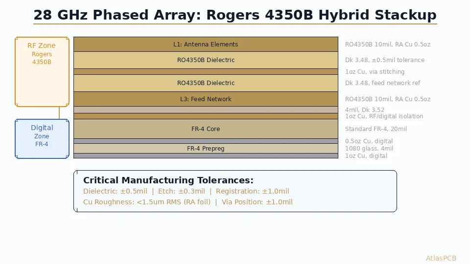
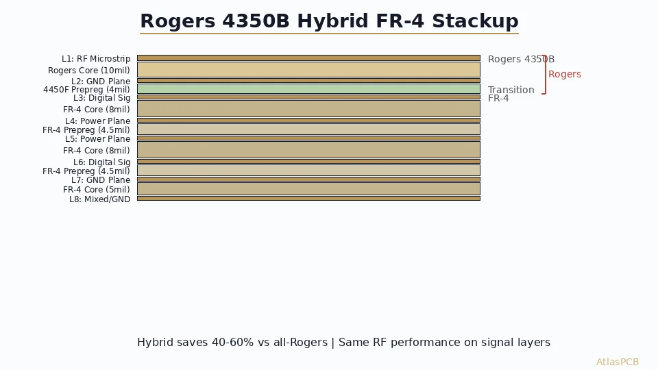
For a typical 8-layer hybrid board serving a 5G small cell or Wi-Fi 6E front-end module, the optimal layer assignment follows this pattern: Layer 1 (top) uses Rogers 4350B at 10mil thickness for microstrip RF traces including PA output matching, antenna feeds, and filter networks. Layer 2 serves as a continuous ground plane on copper bonded to the Rogers core. The transition from Rogers to FR-4 occurs between layers 2 and 3, bonded with Rogers 4450F prepreg at 4mil thickness. Layers 3 through 8 use standard FR-4 construction — digital signal routing on layers 3 and 6, power planes on layers 4 and 5, and another ground reference on layer 7 with a mixed signal/ground on layer 8.
This assignment works because microstrip geometry confines the electromagnetic field between the trace and its immediate reference plane. The Rogers dielectric constant (Dk 3.48) determines the microstrip impedance and propagation velocity only on layers 1-2. The FR-4 beneath has no influence on the RF performance above.
For designs requiring embedded stripline RF (better shielding than microstrip), place Rogers on layers 2 and 3 with ground planes on layers 1 and 4. This sandwiches the RF trace between two ground references with Rogers dielectric on both sides, achieving stripline characteristic impedance defined entirely by the Rogers Dk.
Material Transition: The Critical Interface
The bonding interface between Rogers and FR-4 is the one area where hybrid construction requires engineering attention. Three factors determine a reliable transition:
CTE matching at the boundary is managed by the 4450F prepreg, which has a thermal expansion coefficient midway between Rogers and FR-4. This reduces interlaminar stress during thermal cycling. In our production data across approximately 2,000 hybrid panels, delamination at the Rogers/FR-4 boundary occurs at a rate below 0.1% — comparable to standard all-FR-4 construction.
Resin flow control during lamination requires a modified press program. Rogers cores have zero resin flow (they are fully cured thermosets), while FR-4 cores still flow during lamination. The 4450F prepreg provides the only resin at the transition boundary, so the press program must ensure adequate flow to fill copper relief areas without starving the Rogers interface of adhesion.
Registration accuracy across dissimilar materials is maintained because both Rogers 4350B and FR-4 have similar in-plane dimensional stability during lamination. The X/Y CTE difference (Rogers 10-12 ppm vs FR-4 14-16 ppm) creates less than 0.5mil registration shift across a standard 18x24” panel — well within alignment tolerances for PTH drilling.
IMPEDANCE CONTROLLED MANUFACTURING
+/-5% Impedance on Rogers 4350B Layers
We TDR-verify every impedance-controlled panel with a +/-5% tolerance guarantee on Rogers layers. Standard FR-4 layers held to +/-10%.
RF PCB Capabilities ›Impedance Control: Why Rogers Stackups Hit Tighter Tolerances
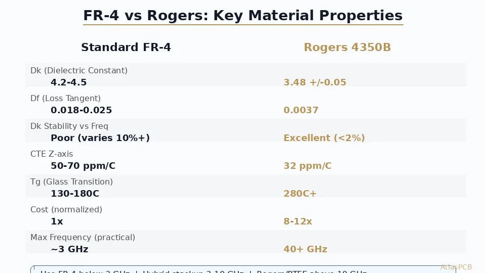
The primary reason hybrid stackups achieve tighter impedance control on Rogers layers is not just the low Dk — it is the Dk stability. Standard FR-4 has a Dk that varies from 4.2 to 4.8 depending on frequency, resin content, glass weave style, and moisture absorption. That variation directly impacts impedance. A 50-ohm design on FR-4 might fabricate anywhere from 45 to 55 ohms due to material batch-to-batch Dk variation alone.
Rogers 4350B specifies Dk 3.48 +/-0.05 — that is +/-1.4% material tolerance compared to +/-7% typical on FR-4. When we run impedance-controlled hybrid panels, our TDR measurements consistently show +/-3% impedance variation on Rogers layers versus +/-7-8% on FR-4 layers in the same board. This difference matters for high-speed serial links where channel compliance requires tight impedance uniformity (PCIe Gen5 specifies +/-5%, USB4 requires +/-7%).
The practical implication: on FR-4 layers, we must pad trace widths by 15-20% to stay within the +/-10% impedance window across material variation. On Rogers layers, we pad by only 5-8%, allowing tighter trace/space rules and higher routing density on the critical RF layers.
Common Hybrid Stackup Examples
8-Layer 5G Small Cell (2.4-6 GHz):
- L1: Rogers 4350B, 10mil — microstrip RF (antenna feeds, PA output)
- Prepreg: Rogers 4450F, 4mil
- L2: Ground plane (full pour)
- L3-L8: Standard Tg170 FR-4, typical digital/power construction
- Total thickness: 62mil (1.57mm)
10-Layer 77 GHz Automotive Radar:
- L1: Rogers 4350B, 5mil — microstrip patch antenna + feed network
- Prepreg: Rogers 4450F, 3mil
- L2: Ground plane
- L3: Rogers 4350B, 5mil — buried stripline RF (beamforming network)
- L4: Ground plane
- L5-L10: Standard FR-4 — digital radar processor, power, CAN bus
- Total thickness: 55mil (1.4mm)
6-Layer Wi-Fi 6E Access Point (5.9-7.1 GHz):
- L1: Rogers 4350B, 8mil — printed antenna elements + matching
- Prepreg: Rogers 4450F, 4mil
- L2: Ground plane
- L3-L6: FR-4, standard digital/power
- Total thickness: 50mil (1.27mm)
Cost Optimization: Getting the Most From Hybrid Construction
Understanding the cost structure of hybrid stackups helps you make the right engineering tradeoffs. Material cost for Rogers 4350B is approximately $85-120 per 18x24” panel at 10mil thickness, compared to $8-12 for equivalent FR-4 core. But material cost is only part of the equation.
The additional processing costs for hybrid construction include: a modified lamination program (adding approximately 30 minutes of setup time per job), one additional material receiving/handling step, and potentially a separate dielectric thickness verification on the Rogers layers. In our facility, these process additions account for roughly $200-400 per lot (typically 5-20 panels), which on a per-board basis is often negligible.
The real cost lever is how many Rogers panels you consume per board. A 4-layer board with Rogers on all layers uses 2 Rogers cores per panel. An 8-layer hybrid uses 1 Rogers core per panel plus 3 FR-4 cores. That single change reduces Rogers material cost by 75% while maintaining identical RF performance on the layer that matters.
Volume pricing further favors hybrid construction. At 100+ panels per order, Rogers 4350B pricing drops 15-25% from spot pricing, and the hybrid premium over all-FR-4 shrinks to approximately 2.5-3x (compared to 3-4x at prototype quantities).
GET A COMPARISON QUOTE
Compare Hybrid vs All-Rogers Pricing
Submit your Gerber files and we will quote both all-Rogers and hybrid stackup options with a recommended approach for your frequency and layer count.
Compare Prices ›Failure Modes: What Goes Wrong in Hybrid Stackups
In our production history, three failure modes account for 85% of hybrid stackup issues — all preventable with proper design practice.
The most common failure is inadequate ground plane continuity at the material transition. When the ground plane between the Rogers and FR-4 sections has cutouts for signal vias, the RF return current must detour around the void. At high frequencies, this detour creates impedance discontinuities and radiating slots. The solution is simple: keep the ground plane at the Rogers/FR-4 boundary as continuous as possible, routing signal vias through other ground layers and using via stitching around any necessary ground plane gaps.
The second failure mode is using incorrect prepreg at the transition interface. We have received designs specifying standard FR-4 prepreg (like 2116) between a Rogers core and FR-4 core. While this will physically bond during lamination, the CTE mismatch creates micro-cracking at the interface after thermal cycling — typically 200-500 reflow cycles before failure. Always specify Rogers 4450F or equivalent bonding film at the Rogers/FR-4 boundary.
Third, designers sometimes route high-frequency signals across the material boundary — starting a trace on a Rogers layer, transitioning through a via, and continuing on an FR-4 layer. This creates a dielectric discontinuity in the middle of the transmission line, causing reflections. If a signal must cross the boundary, add a matched transition structure (ground via ring around the signal via) and accept that the FR-4 segment will have higher loss.
When All-Rogers Actually Makes Sense
Hybrid construction is not universally superior — there are legitimate cases for all-Rogers builds.
Small RF modules with board area under 25x25mm often cost the same whether hybrid or all-Rogers, because panel utilization dominates the cost equation. A tiny all-Rogers 4-layer module might fit 200 per panel, making the per-unit Rogers material cost trivial (roughly $0.50/board). The engineering effort to design a hybrid stackup for such a small board exceeds the cost savings.
Pure RF filter/combiner boards where every layer carries coupled resonators, transmission lines, or distributed elements need uniform dielectric on all layers. A diplexer or bank of cavity filters has no “digital” routing — every trace is RF-critical.
Military/space programs with existing qualified stackups sometimes specify all-Rogers because requalification of a hybrid stackup would cost more than the material savings over the program lifetime.
For everything else — wireless infrastructure, automotive radar, IoT devices, test equipment, instrumentation — hybrid construction is the engineering-optimal choice.
ATLASPCB
Ready to Design Your Rogers 4350B Hybrid Stackup?
Our RF process engineers have fabricated 3,000+ Rogers hybrid panels. Upload your design for a recommended stackup with impedance modeling.
Get Stackup Recommendation ›
Reviewed by AtlasPCB Engineering Team — 15+ years in advanced PCB fabrication for RF, HDI, and rigid-flex applications.
Related Reading:
About AtlasPCB — We specialize in complex PCB manufacturing for HDI, RF, and high-reliability applications. Explore our RF and high-frequency PCB services, or get an impedance-controlled PCB manufacturing . Every order includes free engineering review. Get your quote.
Reviewed by AtlasPCB Engineering Team — IPC-certified manufacturing specialists with 15+ years of production experience in HDI, RF, and high-reliability PCB fabrication. Content based on factory floor data and real customer design reviews.
Frequently Asked Questions
How many Rogers layers do I need in a hybrid stackup?
What prepreg bonds Rogers to FR-4 in a hybrid stackup?
Does a hybrid Rogers/FR-4 stackup require special manufacturing equipment?
What is the cost difference between hybrid and all-Rogers stackups?
Can I achieve 50-ohm impedance on Rogers 4350B with standard trace widths?
- Rogers 4350B stackup
- FR-4 vs Rogers PCB
- RF PCB design
- impedance controlled PCB
- hybrid PCB stackup