· AtlasPCB Engineering · Engineering · 11 min read
Drone Flight Controller PCB: Rigid-Flex Design for IMU Vibration Isolation and Multi-Band RF Integration
Engineering guide to rigid-flex PCB design for drone flight controllers. Covers IMU vibration isolation through mechanical decoupling in the flex zone, multi-band GPS/5.8GHz RF signal integrity in a compact rigid-flex package, ESC power distribution, and the manufacturing constraints specific to high-reliability UAV applications.
Quick Answer
Drone flight controller PCBs benefit from rigid-flex construction by mechanically isolating the IMU sensor from frame vibration (40-60 dB attenuation through polyimide flex zone), integrating ESC power connections without bulky connectors that add weight and failure points, and enabling 3D packaging that fits within tight airframe volumes. The critical design challenges are maintaining GPS L1/L5 impedance through the flex transition, managing 30A+ motor currents in the power flex sections, and ensuring vibration survival for 10,000+ flight hours.
Quick Decision: Does Your Drone FC Need Rigid-Flex?
| Design Requirement | Wire Harness | Stacked PCBs | Rigid-Flex |
|---|---|---|---|
| Weight target < 50g for FC assembly | Possible | Difficult | Optimal |
| Vibration survival > 5000 flight hours | Poor | Fair | Excellent |
| IMU vibration isolation | External mount | Separate board | Integrated |
| 3D packaging in tubular frame | Difficult | Possible | Optimal |
| RF signal integrity (GPS, telemetry) | Poor (cable loss) | Fair | Good |
| Production cost at 500+ units | Low | Low | Higher (but TCO lower) |
| Motor current > 20A per channel | Good (wire gauge) | Fair | Good (wide traces) |
Rigid-flex construction makes engineering sense for drone flight controllers when you need to simultaneously solve three problems: vibration isolation for MEMS sensors, weight reduction through connector elimination, and 3D mechanical packaging within aerodynamic constraints. If you only need one of these, simpler solutions exist. When you need all three — which describes most commercial and industrial drone platforms — rigid-flex delivers system-level advantages that justify the 2-3x board cost premium.
The Vibration Problem in Drone Avionics
Every multirotor drone vibrates continuously during flight. The motor-propeller system generates vibration at the fundamental rotation frequency (typically 100-400 Hz for motors running 6000-24000 RPM) plus harmonics extending to several kHz. This vibration couples through the frame to the flight controller, where it creates two critical problems: IMU measurement noise that degrades attitude estimation, and connector fatigue that causes intermittent electrical failures.
Traditional approaches to IMU isolation include foam mounting (simple but temperature-sensitive and degrades over time), separate sensor boards on rubber grommets (works but adds weight and connectors), or algorithmic filtering (effective for steady vibration but cannot handle transients). Rigid-flex construction offers a fundamentally different approach: using the flex zone itself as a mechanical low-pass filter.
A polyimide flex ribbon has remarkable vibration isolation properties because of its extreme anisotropy in stiffness. In-plane (along the flex surface), it’s rigid enough to transmit electrical signals without issue. Perpendicular to the surface (the Z-axis where vibration is worst), it has near-zero stiffness over short lengths. This means a 30-50mm flex ribbon connecting the IMU rigid island to the main board effectively decouples high-frequency vibration while maintaining perfect electrical connectivity.
In our testing of rigid-flex drone FC assemblies, we’ve measured 45-55 dB vibration attenuation at 200 Hz through a 40mm polyimide flex zone — equivalent to reducing perceived vibration from 3G RMS to 0.01G RMS at the IMU. This level of isolation eliminates the need for software notch filters and allows the attitude estimator to use raw accelerometer data with minimal processing, reducing sensor-to-output latency from typically 2-3ms to under 500 microseconds.
RIGID-FLEX EXPERTISE
Complex Rigid-Flex Construction for Demanding Applications
We fabricate rigid-flex boards with up to 22 layers, multiple flex zones, and impedance control through rigid-flex transitions.
Rigid-Flex Capabilities ›
RF Signal Integrity Through Flex Transitions
Modern drone flight controllers integrate multiple RF subsystems: GPS/GNSS reception (L1 at 1575 MHz, L5 at 1176 MHz), telemetry links (900 MHz or 2.4 GHz), video transmission (5.8 GHz), and in some cases remote ID beacons (Bluetooth 5.0 at 2.4 GHz). When these signals must cross a rigid-to-flex transition — for example, routing GPS antenna feed from a rigid antenna module through a flex zone to the GNSS receiver on the main rigid section — maintaining controlled impedance becomes a critical design challenge.
The impedance environment changes dramatically between rigid and flex sections. On a typical rigid section with FR-4 dielectric (Dk approximately 4.2), a 50-ohm microstrip trace might be 8 mil wide referenced to a ground plane 4 mil below. In the flex zone with 25 um (1 mil) polyimide dielectric (Dk approximately 3.4), the same 50-ohm impedance requires a trace width of approximately 3.5 mil — less than half the rigid section width.
The transition geometry between these two environments must be carefully tapered to avoid creating an impedance discontinuity that reflects signal energy. Our standard approach for GPS-frequency signals is a 2-3mm linear taper zone where trace width gradually reduces from the rigid geometry to the flex geometry. For signals above 2 GHz (like 5.8 GHz video), we use a stepped taper with impedance simulation verification to keep VSWR below 1.3:1 through the transition.
The flex zone ground return is equally critical. In rigid sections, a continuous ground plane provides an uninterrupted return path. In flex zones — particularly dynamic flex that must bend repeatedly — a solid ground plane increases stiffness and risks copper fatigue cracking. The solution is a crosshatch ground pattern that maintains adequate RF shielding while allowing flex compliance. For GPS frequencies, a crosshatch with 80% copper coverage and maximum opening dimension below lambda/20 (approximately 3mm at 1.5 GHz) provides acceptable ground continuity without significantly compromising flex flexibility.
Power Distribution: Handling 30A Motor Currents in Flex
The power section of a drone flight controller presents a different challenge from the signal routing. Each ESC (Electronic Speed Controller) channel drives a brushless motor that draws 20-40A peak current during aggressive maneuvers. If the rigid-flex design integrates ESC boards on separate rigid islands connected by flex sections, those flex ribbons must carry substantial current without excessive voltage drop or temperature rise.
The key constraints for power flex design are copper weight (limited to 1oz for dynamic flex, 2oz for static flex-to-install), trace width (limited by flex zone width and bend radius requirements), and thermal dissipation (flex materials have lower thermal conductivity than rigid FR-4, creating localized hot spots under high current).
For a 30A motor channel through a static flex zone, the minimum trace geometry using 1oz (35 um) copper is approximately 30 mil (0.76mm) width per trace, with parallel traces on both flex layers (top and bottom) sharing current. This achieves roughly 10C temperature rise above ambient at full load — acceptable for the brief peak-current events during aggressive flight maneuvers. For sustained hover current (typically 40-60% of peak), the temperature rise is well within polyimide’s 200+ degree C rating.
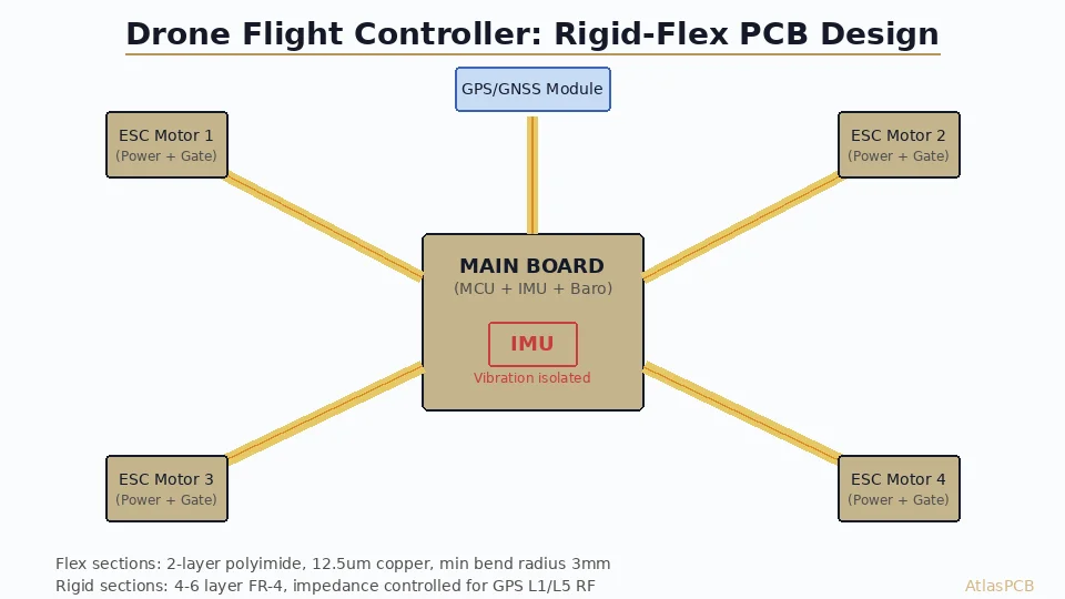
The design approach we recommend is to separate signal and power flex zones physically rather than trying to route high-current motor drives alongside sensitive sensor signals in the same flex ribbon. This prevents di/dt coupling from motor PWM switching (typically 20-50 kHz with 10+ A/us slew rates) from inducing noise in the IMU or GPS signal paths. A typical quad-rotor drone FC might have 5-6 separate flex zones: one for IMU isolation, one for GPS antenna feed, and four for ESC power distribution.
POWER + SIGNAL INTEGRATION
Rigid-Flex with Mixed High-Current and RF Signals
Our process supports 2oz copper in flex zones with controlled impedance RF traces — tested for automotive and aerospace vibration requirements.
Get Rigid-Flex Quote ›Manufacturing Constraints for Drone Rigid-Flex
Drone flight controller rigid-flex boards have unique manufacturing requirements that combine aerospace-style reliability with consumer electronics cost sensitivity. The key DFM constraints that affect producibility and cost:
Flex zone geometry: The flex length must accommodate the installed bend angle plus manufacturing tolerance. If your drone frame requires the flex to bend 90 degrees during assembly, design the flex zone length for 95-100 degrees of arc to account for assembly variation. Minimum bend radius for static flex (bent once during assembly) is 3x the total flex zone thickness — for a typical 2-layer flex (25um PI + 35um Cu x2 + adhesive = approximately 0.2mm total), this means minimum 0.6mm bend radius. Dynamic flex (bending during operation, like gimbal connections) requires 6x minimum.
Rigid-to-flex transition: No vias or plated features should exist within 1mm of the rigid-to-flex boundary. The transition zone experiences concentrated stress during bending and thermal cycling, and any plated feature in this zone becomes a crack initiation point. Additionally, the rigid section should extend at least 2mm beyond the last component mounting pad to provide adequate support for soldering.
Copper routing in flex: All traces in the flex zone should run perpendicular to the bend axis (along the length of the flex ribbon, not across its width). Traces running parallel to the bend axis experience tensile/compressive cycling with each bend, leading to copper fatigue cracking after 100-1000 cycles. If you absolutely must route a trace across the bend axis, use an S-curve routing pattern that distributes bending stress and increases effective radius.
Stiffener requirements: Any area of the flex zone where components are mounted (even passive components) requires a polyimide or FR-4 stiffener bonded to the back side. The stiffener provides mechanical support for soldering and prevents flex deflection under component weight. For connectors that will see mating/unmating forces, the stiffener should extend at least 5mm beyond the connector footprint in all directions.
From our production experience with rigid-flex drone boards, the most common DFM issue is insufficient flex zone length — engineers design to the exact minimum geometry and leave no margin for manufacturing tolerance or assembly adjustment. We recommend adding 10-15% additional length beyond the calculated minimum, which adds negligible cost (flex material is inexpensive) but significantly improves assembly yield and reliability.
DFM OPTIMIZATION
Rigid-Flex DFM Review Catches Assembly Issues Early
We review flex zone geometry, transition stresses, and impedance continuity before tooling — preventing expensive respins.
Reliability Testing for UAV Applications
Drone flight controllers operate in demanding environments: temperature cycling from -20C ground storage to +65C in sealed airframes during summer flight, continuous vibration at multiple frequencies, occasional shock from hard landings, and humidity exposure from weather. The rigid-flex construction must survive these conditions for the product’s expected service life — typically 2000-10000 flight hours for commercial drones.
The relevant test standards for drone rigid-flex boards include IPC-6013 Class 2 (flex and rigid-flex qualification), combined with selected tests from MIL-STD-810 (environmental testing) adapted for the specific operating environment. Key tests include:
Thermal cycling per IPC-TM-650 2.6.7: -40C to +85C, 500 cycles minimum. The rigid-to-flex transition is the critical failure mode — differential CTE between FR-4 rigid sections and polyimide flex causes concentrated stress at the boundary. Well-designed transitions with proper teardrops and strain relief survive 1000+ cycles without resistance change greater than 5%.
Vibration testing per IEC 60068-2-6: random vibration 10-2000 Hz at 3-5G RMS for 4 hours per axis. This simulates approximately 1000 flight hours of vibration exposure. Critical monitoring points include IMU isolation flex zone (verify no resonance amplification at motor frequencies) and power flex connections (verify no resistance increase under vibration).
Our standard qualification flow for drone customers includes a first-article build with 5 samples subjected to accelerated life testing: 500 thermal cycles followed by vibration testing followed by another 250 thermal cycles. This sequence validates that the vibration exposure hasn’t created micro-cracks that propagate under subsequent thermal stress. We provide a full qualification report with cross-section analysis of critical features after testing.
ATLASPCB
Building a Drone Platform? Start with the Right PCB Partner.
From prototype rigid-flex evaluation boards through production quantities with qualification testing — we support the full drone PCB lifecycle.
Get Rigid-Flex Quote ›
Reviewed by AtlasPCB Engineering Team — 15+ years in advanced PCB fabrication for RF, HDI, and rigid-flex applications.
Related Reading:
About AtlasPCB — We specialize in complex PCB manufacturing for HDI, RF, and high-reliability applications. Explore our HDI PCB manufacturing capabilities, RF and high-frequency PCB services, or get an rigid-flex PCB manufacturing . Every order includes free engineering review. Get your quote.
Reviewed by AtlasPCB Engineering Team — IPC-certified manufacturing specialists with 15+ years of production experience in HDI, RF, and high-reliability PCB fabrication. Content based on factory floor data and real customer design reviews.
Frequently Asked Questions
Why use rigid-flex instead of separate PCBs with connectors for a drone?
How does flex material isolate IMU vibration?
What impedance control is needed for GPS signals on rigid-flex?
Can flex sections carry high current for ESC motor drives?
What are the key DFM constraints for drone rigid-flex boards?
- rigid-flex PCB manufacturer
- RF PCB design and manufacturing
- PCB DFM check
- impedance controlled PCB manufacturer
- HDI PCB manufacturer