· AtlasPCB Engineering · Engineering · 8 min read
FR-4 vs Rogers PCB: Complete Material Selection Guide for RF and High-Speed Designs
Compare FR-4 and Rogers 4350B PCB materials across dielectric constant, loss tangent, thermal stability, and cost. Data-driven decision framework for RF engineers choosing between standard and high-frequency laminates.
Quick Answer
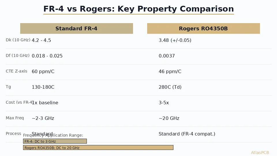
Use FR-4 for digital designs below 3 GHz where cost matters most. Switch to Rogers 4350B when your signal frequency exceeds 3 GHz, insertion loss budget is tight (less than 0.5 dB/inch at operating frequency), or you need Dk stability across temperature for phase-critical applications like phased arrays. The cost premium is 3-5x on material alone, but Rogers eliminates the need for over-engineering margins that FR-4's Dk variation (4.2-4.5 vs Rogers' 3.48 +/-0.05) forces on your impedance structures.
Quick Decision: FR-4 or Rogers?
| Criterion | FR-4 Sufficient | Rogers 4350B Required |
|---|---|---|
| Operating frequency | < 3 GHz | > 3 GHz |
| Insertion loss budget | > 1 dB/inch | < 0.5 dB/inch |
| Dk stability over temp | Not critical | Phase-critical |
| Trace length (RF path) | < 2 inches | > 2 inches at freq > 5 GHz |
| Application | Digital, power, low-speed analog | RF front-end, phased array, radar |
| Budget priority | Cost-driven | Performance-driven |
| Volume | High volume consumer | Low-mid volume telecom/defense |
If your design hits frequency above 3 GHz on any critical signal path, specify Rogers. The cost premium pays for itself in eliminated design iterations and field reliability.
Understanding the Material Difference
The fundamental distinction between FR-4 and Rogers comes down to what happens to your electromagnetic wave as it propagates through the dielectric. FR-4 is a woven glass cloth impregnated with epoxy resin — a composite material never designed for RF performance. The glass weave creates a non-homogeneous dielectric where the effective Dk varies depending on whether your trace runs parallel to the weave, at 45 degrees, or perpendicular. This weave effect introduces Dk variation of 0.3-0.5 units across the panel, making precise impedance control a statistical exercise rather than an engineering certainty.
Rogers 4350B uses a ceramic-filled hydrocarbon thermoset — no glass weave, no epoxy. The result is a homogeneous dielectric with Dk variation of only +/-0.05 across a panel and from lot to lot. For an impedance-controlled trace, this means your fabricated impedance will be within 2-3% of simulation, compared to 8-12% variation typical on FR-4 at frequencies above 5 GHz.
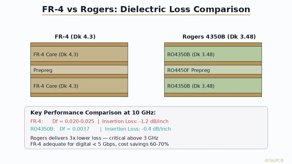
The loss tangent difference is equally stark. At 10 GHz, FR-4’s Df of 0.020-0.025 versus Rogers’ 0.0037 translates to roughly 3x the signal attenuation per unit length. In our production, we regularly measure 50-ohm microstrip on Rogers 4350B with insertion loss of -0.38 dB/inch at 10 GHz, while the same geometry on standard FR-4 measures -1.15 dB/inch. That difference becomes critical when your link budget allows only 3-5 dB total loss across the RF chain.
RF PCB SPECIALISTS
Not Sure Which Material Fits Your Design?
Our RF engineers review your stackup requirements and recommend the optimal material combination — including hybrid builds that save cost without sacrificing performance.
Get Material Recommendation ›
Thermal Stability and Environmental Performance
Temperature stability separates Rogers from FR-4 in ways that matter beyond the lab bench. In our thermal cycling tests (1000 cycles, -40C to +125C), Rogers 4350B maintains Dk within 0.02 units of its room-temperature value. FR-4, by contrast, drifts by 0.15-0.20 units over the same temperature range, with the drift being non-linear and unpredictable above its glass transition temperature.
For automotive radar at 77 GHz, this thermal Dk drift directly translates to beam steering error in antenna arrays. A 0.1 unit Dk shift changes the electrical length of a quarter-wave element by roughly 1.5%, which at 77 GHz means 0.4mm of phase error — enough to degrade angular resolution by 2-3 degrees. This is why every automotive radar PCB we manufacture uses Rogers or equivalent PTFE-based materials on the antenna layers.
Moisture absorption tells a similar story. FR-4 absorbs 0.10-0.15% moisture by weight at equilibrium in 50% relative humidity, and that moisture increases both Dk and Df measurably. Rogers 4350B absorbs only 0.06%, and its hydrocarbon chemistry is far less sensitive to moisture-induced property changes. For outdoor telecom equipment or marine electronics, this difference eliminates a failure mode that would otherwise require expensive hermetic sealing.
CHINA RF PCB MANUFACTURER
Rogers 4350B In Stock — 5-Day Quick Turn
We maintain inventory of RO4350B and RO4003C in standard thicknesses. No 6-week material lead time on your prototype run.
View RF Capabilities ›Cost Analysis: When the Premium Makes Sense
Let’s talk real numbers. A 4-layer Rogers 4350B board at 100x50mm in quantity 10 typically costs $45-65 per piece from a qualified RF fabricator, versus $8-15 for the same geometry in standard FR-4. That’s a 4-6x multiplier on the bare board. However, the total system cost equation often favors Rogers when you factor in:
First, impedance tolerance. On FR-4, achieving +/-5% impedance control at 10 GHz requires extensive simulation, multiple design iterations, and test coupon verification on every panel. On Rogers, +/-5% is routine — the material consistency does the work. We see customers save 2-3 revision cycles (each costing $2,000-5,000 in NRE and time) by specifying Rogers upfront for RF sections.
Second, yield. In our facility, first-pass yield on Rogers RF boards averages 94% versus 87% for demanding RF designs attempted on enhanced FR-4. The yield gap widens as frequency increases and trace geometries shrink.
Third, field reliability. A phased array antenna that drifts out of spec at temperature extremes costs far more to recall and rework than the material premium on Rogers. For defense and telecom infrastructure, the reliability math always favors ceramic-filled laminates.
The sweet spot for hybrid designs — Rogers on RF layers, FR-4 on digital/power layers — typically lands at 2.5-3x the cost of an all-FR-4 board, delivering 90% of the RF performance at 50% of the cost of an all-Rogers build.
Processing and Manufacturability Considerations
Rogers materials process differently than FR-4, and these differences affect both yield and lead time. The thermoset hydrocarbon chemistry has a narrower processing window for drilling, plating, and lamination. Drill speeds must be reduced 20-30% to avoid smearing, and desmear chemistry differs from standard permanganate processes used on FR-4.
In our production, we run Rogers panels on dedicated drill machines with ceramic-backed entry material and specific spindle speeds calibrated for each Rogers product variant. The copper bonding on Rogers is also different — most Rogers products use reverse-treated (RT) foil with a specialized treatment that achieves peel strength above 6 lb/in, compared to standard electrodeposited foil used on FR-4.
For hybrid stackups combining Rogers and FR-4, the lamination profile is the critical step. The Rogers layers bond at lower temperatures (375-385F) than standard FR-4 prepreg (350-365F), and the two materials have different flow characteristics. Our process engineers developed a staged lamination cycle that brings the Rogers layers to bond temperature first, then ramps to cure the FR-4 prepreg — preventing delamination at the material interface that plagued our early hybrid builds.
IMPEDANCE CONTROLLED PCB MANUFACTURER
Hybrid Rogers + FR-4 Stackups Built Daily
Proven lamination profiles for Rogers/FR-4 hybrid builds. Impedance control to +/-5% with TDR verification on every panel.
Decision Framework: Material Selection by Application
For engineers making this decision today, here is the framework we use when consulting on material selection:
Use FR-4 when: Your highest-frequency signal is below 3 GHz, board area is cost-sensitive (consumer IoT, white goods), impedance tolerance of +/-10% is acceptable, and the product operates in a controlled thermal environment (0-70C).
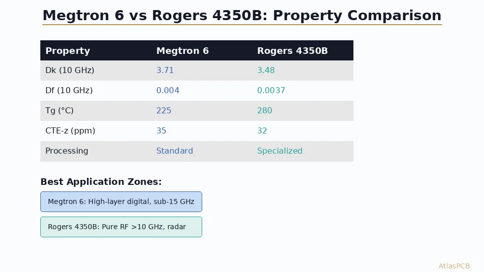
Use enhanced FR-4 (Megtron 4/6, Tachyon 100G) when: Digital signals run at 10-28 Gbps (PCIe Gen 4/5, 100G Ethernet), you need Df below 0.008 but don’t have strict Dk stability requirements, and cost must stay below 2x standard FR-4.
Use Rogers 4350B when: RF signals operate at 3-30 GHz, impedance tolerance must be +/-5% or better, temperature stability matters for outdoor or automotive deployment, and you need consistent lot-to-lot reproducibility for production volumes.
Use PTFE (Rogers RT/duroid, Taconic TLY) when: Operating frequency exceeds 30 GHz (automotive radar, 5G mmWave, satellite Ka-band), loss tangent must be below 0.002, and the design can tolerate PTFE’s processing challenges (poor adhesion, dimensional instability).
ATLASPCB
Ready to Finalize Your RF Material Selection?
Send us your stackup requirements. Our engineers will recommend the optimal material combination and provide a detailed quote within 24 hours — including hybrid Rogers/FR-4 builds.
Get Instant Quote ›
Reviewed by AtlasPCB Engineering Team — 15+ years in advanced PCB fabrication for RF, HDI, and rigid-flex applications.
Related Reading:
About AtlasPCB — We specialize in complex PCB manufacturing for HDI, RF, and high-reliability applications. Explore our RF and high-frequency PCB services, Rogers RO4350B PCB manufacturing, or get an impedance-controlled PCB manufacturing . Every order includes free engineering review. Get your quote.
Reviewed by AtlasPCB Engineering Team — IPC-certified manufacturing specialists with 15+ years of production experience in HDI, RF, and high-reliability PCB fabrication. Content based on factory floor data and real customer design reviews.
Frequently Asked Questions
At what frequency should I switch from FR-4 to Rogers?
Can I mix FR-4 and Rogers in the same stackup?
Is Rogers 4350B worth the cost for a 5 GHz WiFi design?
What about Rogers alternatives like Taconic or Isola?
- FR-4
- Rogers 4350B
- RF PCB
- high-frequency PCB
- dielectric loss
- PCB material selection
- impedance control