· AtlasPCB Engineering · Engineering · 9 min read
JLCPCB vs Custom PCB Manufacturer for Impedance-Controlled Boards: Where Budget Services Fall Short
Comparing JLCPCB's standard impedance capabilities against dedicated custom manufacturers for controlled-impedance designs. Real tolerance data, material options, and the cost of impedance failures.
Quick Answer
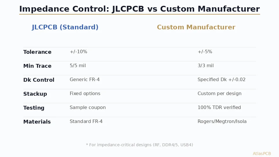
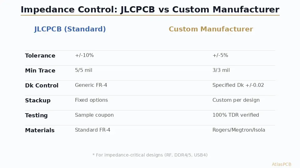
JLCPCB offers +/-10% impedance tolerance on standard FR-4 with fixed stackups, while custom manufacturers deliver +/-5% (or tighter) with specified dielectric constants, 100% TDR verification, and material flexibility including Rogers and Megtron — making custom manufacturers essential for any design above 3 GHz or DDR4/5 routing.
Quick Decision: JLCPCB or Custom Manufacturer for Impedance Control?
| Criteria | JLCPCB | Custom Manufacturer |
|---|---|---|
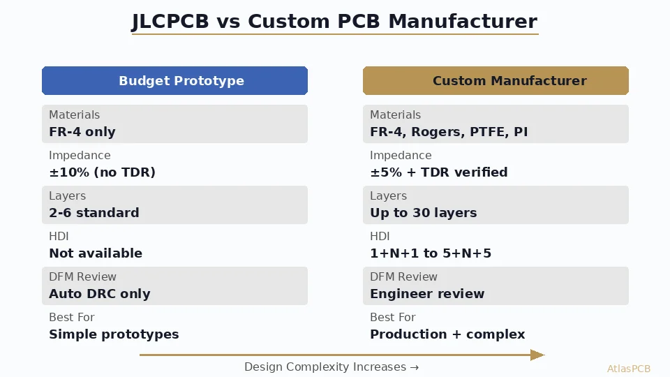
| Impedance Tolerance | +/-10% | +/-5% (or +/-3% on request) |
| Dk Specification | Generic FR-4 (Dk 4.2-4.8) | Specified laminate (Dk +/-0.02) |
| Verification Method | Sample coupon on panel edge | 100% TDR on every production board |
| Min Trace/Space | 5/5 mil | 3/3 mil (75um) |
| Material Options | Standard FR-4, limited Rogers | Rogers, Megtron, PTFE, Isola, hybrid |
| Stackup Flexibility | Fixed templates | Custom per design requirements |
| Best For | Prototypes below 1 GHz | Production boards, RF, high-speed digital |
If your design operates below 1 GHz with single-ended traces on standard FR-4, JLCPCB’s impedance service works adequately for prototyping. The moment you need differential pairs above 3 Gbps, RF transmission lines, or DDR4/5 routing with tight length matching, a custom impedance-controlled PCB manufacturer becomes non-negotiable.
The Real Problem with Budget Impedance Control
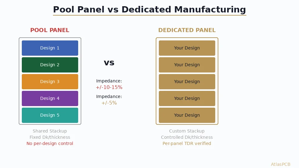
The fundamental issue with JLCPCB’s impedance service is not that they cannot hit a target — it is that you cannot verify what you received. When a board house uses generic FR-4 laminate sourced from whichever supplier had stock that week, the dielectric constant can swing between 4.2 and 4.8 depending on resin content, glass weave style, and cure conditions. A 50-ohm microstrip designed for Dk=4.4 will measure anywhere from 46 to 54 ohms if the actual Dk drifts to the edges of that range.
In our facility, we run incoming inspection on every laminate lot and track Dk values to +/-0.02. We have seen batches of nominally identical FR-4 from the same manufacturer differ by 0.15 in measured Dk — enough to push a 100-ohm differential pair outside the +/-10% window that JLCPCB guarantees. The difference is that a custom manufacturer specifies the exact laminate grade (say, Shengyi S1000-2M at Dk=4.25 +/-0.05 @ 1 GHz) and verifies it before lamination.
For engineers designing anything operating above 3 GHz — think Wi-Fi 6E, 5G front-end modules, automotive radar IF stages, or USB4 retimers — the uncontrolled Dk variation from budget services creates insertion loss uncertainty that no amount of simulation accuracy can overcome. Your 2D field solver gives you a beautiful 50.0 ohms on paper, but the fabricated board might land at 47 or 53 ohms because the dielectric properties were never actually specified.
IMPEDANCE-CONTROLLED PCB MANUFACTURING
Need +/-5% Impedance or Tighter?
Upload your stackup requirements. Our engineers specify exact laminate grades and verify every board with TDR.
Get Impedance Quote ›
Where JLCPCB’s Impedance Service Actually Works
Credit where it is due: JLCPCB handles millions of impedance-controlled boards per year for a reason. Their service works well for prototyping sub-GHz designs where you need the traces to be approximately correct. If you are routing a UART at 115200 baud or an SPI bus at 10 MHz, impedance control barely matters — and JLCPCB’s +/-10% tolerance is more than adequate for verifying your layout before committing to production tooling.
The typical workflow that makes sense: prototype on JLCPCB at $50 to validate functionality, then move to a custom manufacturer for production where you need guaranteed performance. We see this pattern across probably 40% of our new customers — they come to us after their JLCPCB prototype worked on the bench but failed FCC testing or showed eye diagram closure at temperature extremes.
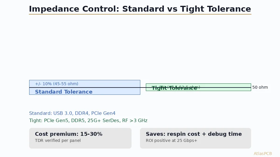
The trigger points for switching are predictable. DDR4 at 2400 MT/s can tolerate sloppy impedance if your traces are short (under 1 inch). DDR5 at 4800+ MT/s cannot — the tighter timing margins and lower voltage swings demand +/-5% impedance matching across all bytes simultaneously. Similarly, USB 3.2 Gen 1 (5 Gbps) is forgiving, but USB4 (40 Gbps) requires TDR-verified impedance continuity through every via transition and connector breakout.
TDR Verification: The Critical Difference
The single biggest technical differentiator between a budget PCB service and a custom impedance-controlled manufacturer is verification methodology. JLCPCB, like most high-volume shops, verifies impedance using a test coupon located at the panel edge. This coupon contains a representative trace matching your specified width and spacing, and it gets measured with a flying probe or dedicated impedance tester.
The problem? The coupon is not your board. Copper thickness variation across a panel can reach +/-10% from center to edge. Prepreg flow characteristics differ near panel borders due to resin starvation at tooling holes. A coupon passing at 50.2 ohms does not guarantee that the trace running through your BGA breakout — surrounded by dense copper pours that alter effective Dk through the glass weave — also measures 50 ohms.
In our production process, we run 100% TDR on impedance-critical nets for any design specifying +/-5% or tighter. This means a time-domain reflectometer scans every controlled trace on every panel, flagging any excursion beyond the tolerance window. The failure rate we catch with board-level TDR that would have passed coupon-only inspection runs about 3-5% on complex HDI designs. For a 1000-piece production run, that is 30-50 boards you would have shipped to customers with out-of-spec impedance.
100% TDR VERIFICATION
Every Board. Every Controlled Net.
We catch the 3-5% of boards that pass coupon inspection but fail on-board TDR. Zero out-of-spec boards ship.
See Our Test Capabilities ›Material Flexibility: Beyond Standard FR-4
JLCPCB’s material selection is fundamentally constrained by their business model. High-volume, low-mix production requires standardized material inventory. You get their default FR-4 (typically a Shengyi or Nanya mid-grade laminate), with Rogers 4350B available at extended lead times and significant premiums — but only in their pre-defined stackup configurations.
A custom impedance-controlled PCB manufacturer maintains relationships with multiple laminate suppliers and stocks a range of dielectric materials. When your design requires Rogers 4350B on the outer layers for a 5G front-end but standard FR-4 in the core for cost optimization, a custom house builds that hybrid stackup routinely. When you need Panasonic Megtron 6 for a 112G PAM4 backplane with Dk=3.4 and Df=0.002 at 10 GHz, they source it and adjust their process parameters accordingly.
The material difference becomes critical for thermal reliability as well. JLCPCB’s standard FR-4 typically has a Tg of 130-150C. For automotive under-hood applications requiring continuous 125C operation, you need high-Tg material (Tg 170C+) with specific CTE characteristics. A custom manufacturer specifies and sources Isola 370HR, Shengyi S1000-2M, or equivalent — and certifies the incoming material properties match the design intent.
MATERIAL SELECTION SUPPORT
Rogers, Megtron, PTFE, Hybrid Stackups
Tell us your frequency and loss budget. We recommend the optimal material and stackup configuration.
Cost Analysis: When “Cheap” Becomes Expensive
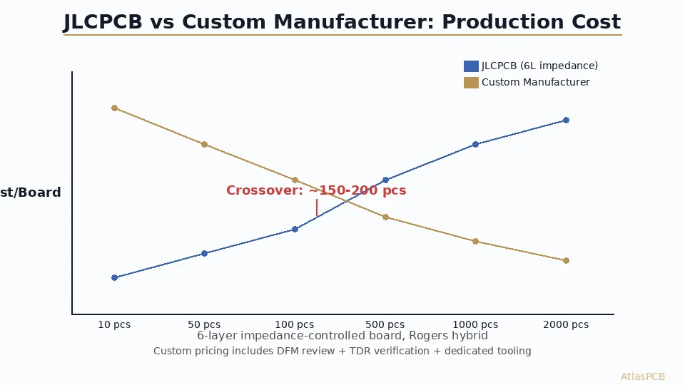
The price gap between JLCPCB and a custom impedance-controlled manufacturer is real — expect 40-80% higher unit cost for a typical 6-layer controlled-impedance board. On a 100-piece prototype run of 100x100mm boards, that might translate to $18/board at JLCPCB versus $28-32/board from a dedicated custom manufacturer.
But the math changes completely when you factor in failure costs. A single board respin for an impedance issue costs $5,000-15,000 in engineering time, new tooling, and schedule delay. A field failure in deployed product — where a DDR5 interface shows marginal timing at 85C because impedance drifted out of spec — can cost orders of magnitude more in warranty returns, customer credibility, and firmware workarounds.
We track first-pass yield on impedance-controlled boards at approximately 97% with our process (100% TDR, specified materials, process controls). Customers who come to us after JLCPCB production failures typically report 85-90% functional yield on their impedance-sensitive designs from budget sources — not because the boards are defective, but because 10-15% of boards have impedance excursions that cause intermittent behavior in high-speed interfaces.
Decision Framework: Which Service for Your Project
The right choice depends on your specific design requirements, not a blanket recommendation. Use this decision framework:
Stay with JLCPCB when: Your maximum signal frequency is below 1 GHz, traces are shorter than 2 inches, you are prototyping only (not production), and you can tolerate +/-10% impedance variation without functional impact. Also appropriate for designs where impedance control is specified “just in case” but signal integrity simulations show ample margin.
Move to a custom manufacturer when: You need differential pairs above 5 Gbps, RF traces above 2 GHz, DDR4-3200 or faster memory routing, USB4/Thunderbolt 4 interfaces, or any design going into production where field reliability matters. Also mandatory when your design requires non-standard materials, hybrid stackups, or impedance tighter than +/-7%.
The hybrid approach that works: Prototype 2-3 boards on JLCPCB for functional validation. Once the design is frozen, move to a custom manufacturer for the pilot run with full TDR verification. Use the TDR data to confirm your simulation models are accurate before committing to volume production.
ATLASPCB
Ready to Move Beyond Budget Impedance?
Upload your Gerber files and stackup. We provide impedance simulation, material recommendation, and quoted pricing within 24 hours.
Get Custom Quote ›
Reviewed by AtlasPCB Engineering Team — 15+ years in advanced PCB fabrication for RF, HDI, and rigid-flex applications.
Related Reading:
About AtlasPCB — We specialize in complex PCB manufacturing for HDI, RF, and high-reliability applications. Explore our RF and high-frequency PCB services, or get an impedance-controlled PCB manufacturing . Every order includes free engineering review. Get your quote.
Reviewed by AtlasPCB Engineering Team — IPC-certified manufacturing specialists with 15+ years of production experience in HDI, RF, and high-reliability PCB fabrication. Content based on factory floor data and real customer design reviews.
Frequently Asked Questions
What impedance tolerance does JLCPCB offer?
When should I switch from JLCPCB to a custom PCB manufacturer?
How much more does impedance-controlled PCB manufacturing cost from a custom manufacturer?
Does JLCPCB offer Rogers or other high-frequency materials?
- pcb-manufacturing
- impedance-control
- jlcpcb-comparison
- rf-design