· AtlasPCB Engineering · Engineering · 11 min read
Rogers 4350B vs Megtron 6: Choosing the Right Laminate for Impedance Controlled PCBs Above 10 GHz
A head-to-head comparison of Rogers RO4350B and Panasonic Megtron 6 for high-frequency impedance controlled PCB designs. Covers Dk stability, loss tangent, hybrid stackup strategies, and cost tradeoffs for 10-28 GHz applications including 5G infrastructure and automotive radar.
Quick Answer
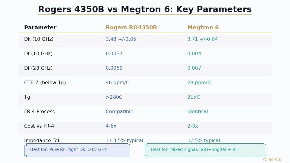
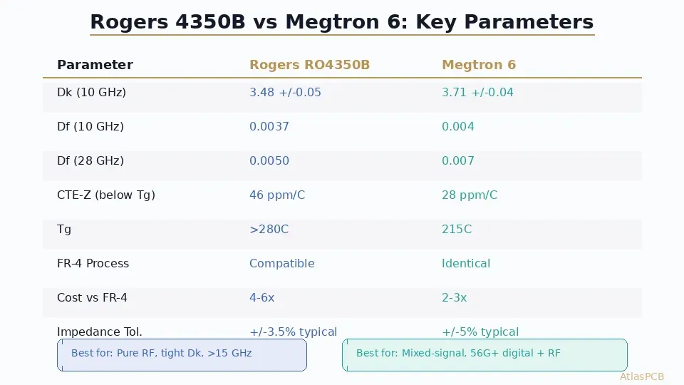
Rogers RO4350B delivers superior Dk stability (3.48 +/-0.05) and lower loss tangent (0.0037 at 10 GHz) compared to Megtron 6 (Dk 3.71 +/-0.04, Df 0.004 at 10 GHz). For pure RF designs above 15 GHz, Rogers wins. For mixed-signal boards where digital channels run at 56+ Gbps alongside moderate RF paths, Megtron 6 offers a compelling middle ground with FR-4-compatible processing and lower material cost.
Quick Answer: Rogers 4350B vs Megtron 6
| Parameter | Rogers RO4350B | Panasonic Megtron 6 |
|---|---|---|
| Dk (10 GHz) | 3.48 +/-0.05 | 3.71 +/-0.04 |
| Df (10 GHz) | 0.0037 | 0.004 |
| Df (28 GHz) | 0.0050 | 0.007 |
| Z-axis CTE (below Tg) | 46 ppm/C | 28 ppm/C |
| Tg | 280C+ | 215C |
| FR-4 process compatible | Yes | Yes (identical) |
| Cost vs FR-4 | 4-6x | 2-3x |
| Best for | Pure RF, tight Dk tolerance | Mixed-signal, high-speed digital + moderate RF |
| Impedance tolerance (production) | +/-5% routine, +/-3.5% typical | +/-7% routine, +/-5% with tight process |
Why This Comparison Matters Now
The proliferation of 5G infrastructure, automotive radar modules, and high-speed computing platforms has created a design space where engineers face a genuinely difficult material decision. Five years ago, the choice was simple: if your board had RF content above 5 GHz, you used Rogers. Everything else got FR-4. Today, the emergence of very-low-loss FR-4 alternatives — particularly Panasonic’s Megtron 6 and Megtron 7 — has blurred that boundary considerably.
Engineers designing impedance controlled PCBs for applications in the 10-28 GHz range now must weigh material performance against total system cost, manufacturing complexity, and supply chain reliability. Rogers RO4350B remains the gold standard for pure RF performance, but Megtron 6 has carved out a legitimate position for boards that combine high-speed serial links (56-112 Gbps PAM4) with moderate RF functionality.
In our facility, we fabricate roughly equal volumes of both materials for impedance-controlled designs. The boards that benefit most from Rogers tend to be antenna feed networks, radar front-ends, and satellite communication modules where every 0.001 of loss tangent matters. Megtron 6 dominates in switch fabric boards, AI accelerator substrates, and 5G baseband units where the digital channels are the primary concern but RF filtering or local oscillator distribution requires controlled impedance paths.
IMPEDANCE CONTROLLED PCB MANUFACTURING
Need +/-5% Impedance on Rogers or Megtron?
We run TDR verification on every RF panel. Upload your stackup for a material recommendation and quote.
Upload Stackup ›
Dielectric Performance: The Numbers That Matter
Dk Stability Across Frequency
The critical differentiator between these materials becomes apparent when you examine Dk variation from 1 GHz to 40 GHz. Rogers RO4350B maintains a remarkably flat dielectric constant — the datasheet specifies 3.48 at 10 GHz measured via clamped stripline, and in practice we see less than 2% variation from 1 GHz to 30 GHz on production boards. This predictability is what makes Rogers the preferred substrate for narrowband filter designs and phased array feed networks where phase consistency across frequency determines antenna pattern integrity.
Megtron 6, being a modified epoxy system rather than a ceramic-filled hydrocarbon, exhibits more frequency-dependent Dk behavior. At 1 GHz, Megtron 6 measures approximately 3.8, dropping to 3.71 at 10 GHz and continuing a gradual decline to about 3.65 at 28 GHz. For broadband digital channels using PAM4 signaling, this gradual slope is actually well-characterized and predictable — modern channel simulation tools like Keysight ADS and Ansys HFSS model it accurately. The problem arises in narrowband RF applications where the filter or matching network was designed assuming a specific Dk value.
Loss Tangent and Its Impact on Link Budget
At 10 GHz, the 0.0003 difference in loss tangent between Rogers (0.0037) and Megtron 6 (0.004) translates to approximately 0.02 dB/cm additional insertion loss for a 50-ohm microstrip on Megtron 6. Over a typical 5 cm RF trace run, that adds up to 0.1 dB. For many applications, 0.1 dB is negligible. But in a 77 GHz automotive radar front-end where you have 15 cm of total feed network length and a link budget already constrained to tenths of a dB, that material choice directly impacts detection range.
Where the gap widens dramatically is at mmWave frequencies. At 28 GHz, Rogers maintains Df around 0.005 while Megtron 6 climbs to approximately 0.007. At 77 GHz, we have measured Rogers performing at Df 0.006-0.007 while Megtron 6 reaches 0.010-0.012. This makes Megtron 6 effectively unusable above 40 GHz for anything except very short trace runs.
Manufacturing Considerations for Impedance Control
Process Compatibility
Both Rogers 4350B and Megtron 6 process using standard FR-4 fabrication equipment — this is their shared advantage over PTFE materials like Rogers RO5880, which require sodium-etched surface preparation and cannot use standard oxide treatments for copper adhesion.
However, the subtlety lies in lamination parameters. Rogers 4350B requires precise temperature control during pressing: a peak temperature of 375-385F held for 90 minutes under 300-400 PSI. Deviation beyond this window affects the final Dk value. Our lamination engineers maintain statistical process control charts specifically for Rogers press cycles, and we have observed that boards pressed at the high end of the temperature window consistently measure 0.02-0.03 higher Dk than those at the low end. This level of detail matters when you are targeting +/-3% impedance tolerance.
Megtron 6 presses identically to FR-4 at 355-365F — no special profiles needed. This means any fabricator comfortable with standard multilayer processing can handle Megtron 6 without process development. The consistency advantage is real: in our production data, Megtron 6 panels show lower panel-to-panel impedance variation than Rogers (standard deviation of 1.8% vs 2.3% on production lots) primarily because the lamination process window is wider.
Impedance Tolerance Achievement
For impedance controlled PCB manufacturing, the achievable tolerance depends on the interaction between material Dk consistency, etching uniformity, and dielectric thickness control.
With Rogers 4350B, we routinely achieve +/-5% impedance tolerance on single-ended 50-ohm lines and differential 100-ohm pairs. On boards where the customer specifies controlled impedance on external microstrip layers, our statistical data shows average deviation of 3.5% from target — well within the +/-5% specification. The key enabler is that Rogers’ tight Dk tolerance means impedance variation is dominated by etching factors (trace width, copper thickness) rather than material uncertainty.
Megtron 6 requires slightly more conservative design rules to achieve the same tolerance. Because Dk variation is approximately +/-1.0% (compared to Rogers’ +/-1.5% in absolute terms, but from a smaller baseline), the combined uncertainty from material and etch factors typically yields +/-7% tolerance without special controls. To achieve +/-5% on Megtron 6, we employ test-coupon TDR verification and adjust etch compensation on a per-lot basis — adding a small amount of cost but delivering consistent results.
CHINA RF PCB MANUFACTURING
Rogers and Megtron 6 In-Stock
We maintain local inventory of RO4350B (6.6mil, 10mil, 20mil) and Megtron 6 cores. No 8-week lead time surprises.
View Capabilities ›Stackup Design Strategies
Rogers 4350B Hybrid Stackup (Recommended for RF-Dominant Designs)
The most cost-effective approach for boards with RF content is a hybrid stackup using Rogers 4350B on the RF signal layers and standard FR-4 or Megtron 4 on digital layers. A typical 8-layer hybrid for a 5G small cell front-end looks like this:
Layer 1 (Top): Rogers RO4350B 6.6mil — RF transmission lines, antenna feed Layer 2 (GND): Copper ground plane (continuous) Layer 3 (Signal): FR-4 Megtron 4 — digital control signals Layer 4 (PWR): Power distribution Layer 5 (PWR): Power distribution Layer 6 (Signal): FR-4 Megtron 4 — digital signals Layer 7 (GND): Copper ground plane (continuous) Layer 8 (Bottom): Rogers RO4350B 6.6mil — RF transmission lines
This stackup places Rogers where it matters (external microstrip layers with RF content) while using lower-cost material for internal digital routing. The cost premium over all-FR-4 is typically 80-120% rather than the 300-400% of an all-Rogers construction.
The critical design consideration is the Rogers-to-FR-4 transition. At our facility, we use Rogers RO4450F prepreg (specifically designed as a bonding film for RO4350B) to attach the Rogers cores to the FR-4 inner assembly. This prepreg has matched CTE and thermal stability to prevent delamination during reflow soldering. We have validated this construction through 1000+ thermal cycles (-40C to +125C) with zero delamination failures across hundreds of production lots.
Megtron 6 Full-Stack (Recommended for High-Speed Digital + Moderate RF)
For PCB designs requiring both high-speed serial links and moderate RF content, a full Megtron 6 stackup simplifies manufacturing while providing adequate RF performance up to 15-20 GHz. A 12-layer networking switch board might use:
Layers 1-12: All Megtron 6 cores and prepreg
- Signal layers: 100-ohm differential pairs for 56G PAM4 SerDes
- RF layers: Local oscillator distribution at 12.5 GHz
- Impedance tolerance: +/-7% all layers, +/-5% on critical RF pairs with TDR verification
The advantage of this approach is manufacturing simplicity. One material system means one press profile, one set of etch compensation factors, and consistent impedance behavior across all layers. For high-volume production (1000+ panels/month), this simplification translates directly to higher yield and lower per-unit cost.
Real-World Application Decision Matrix
| Application | Frequency | Recommended Material | Rationale |
|---|---|---|---|
| 77 GHz automotive radar | 76-81 GHz | Rogers 4350B (or RO3003) | Loss tangent critical at mmWave |
| 5G FR2 antenna module | 24-28 GHz | Rogers 4350B hybrid | Dk stability for beam steering |
| 5G sub-6 GHz radio unit | 3.5-6 GHz | Megtron 6 or hybrid | Loss budget adequate |
| 400G switch fabric | Baseband (28 Gbaud) | Megtron 6 | Digital focus, no RF |
| Satellite Ka-band | 26-40 GHz | Rogers 4350B or 3003 | Cannot compromise Dk stability |
| WiFi 6E access point | 5-7 GHz | FR-4 (Megtron 4) or Megtron 6 | Cost-sensitive, moderate performance |
| AI accelerator interposer | 112G PAM4 | Megtron 6 or 7 | Ultra-low-loss digital, no RF |
STACKUP DESIGN SUPPORT
Not Sure Which Material Fits Your Design?
Our RF engineers review stackup proposals and recommend optimal material combinations based on your frequency, loss budget, and volume requirements.
Get Recommendation ›Cost Analysis and Supply Chain Considerations
Material cost is only part of the equation. When comparing Rogers 4350B and Megtron 6 for an impedance controlled PCB, you must factor in yield implications, lead times, and volume pricing tiers.
Rogers Corporation maintains a distributor network with relatively predictable pricing. Standard RO4350B cores in popular thicknesses (6.6mil, 10mil, 20mil, 30mil) typically ship within 2-3 weeks from distributor stock in Asia. However, non-standard thicknesses or large volume orders can extend to 6-8 weeks. In China, we maintain local inventory of the three most popular thicknesses specifically to avoid this delay for our customers.
Megtron 6 pricing follows Panasonic’s distribution model, which in China means slightly longer baseline lead times (3-4 weeks) but better volume discount structures. For orders exceeding 100 panels per month, Megtron 6 becomes surprisingly cost-competitive — often only 1.8-2.2x FR-4 rather than the 2.5-3x at prototype quantities.
From a yield perspective, both materials achieve similar first-pass yield in our facility (94-96% for 8-layer controlled impedance boards). The yield delta that did exist historically — Rogers boards failing at slightly higher rates due to lamination sensitivity — has been eliminated through our proprietary press profile optimization. We invested in pressure mapping and real-time temperature monitoring that reduced Rogers yield loss from 8% to under 4% over the past two years.
Making the Decision
If your design operates primarily above 15 GHz with tight loss and impedance budgets, Rogers 4350B remains the correct choice. If you are building a mixed-signal platform where high-speed digital is the primary concern and RF content is supplementary (below 15 GHz), Megtron 6 delivers 85% of Rogers’ RF performance at 50-60% of the material cost.
For engineers still uncertain, our standard recommendation is to begin with a hybrid Rogers stackup for the first prototype, characterize actual insertion loss on a test coupon, and then evaluate whether a Megtron 6 substitution is viable for production. This costs one additional prototype iteration but eliminates the risk of choosing the wrong material and discovering it 6 weeks into a production run.
ATLASPCB
Ready to Build Your RF Board?
Upload your Gerber files and stackup spec. We quote Rogers 4350B and Megtron 6 options side-by-side so you can compare cost and lead time directly.
Get Instant Quote ›
Reviewed by AtlasPCB Engineering Team — 15+ years in advanced PCB fabrication for RF, HDI, and rigid-flex applications.
Related Reading:
About AtlasPCB — We specialize in complex PCB manufacturing for HDI, RF, and high-reliability applications. Explore our RF and high-frequency PCB services, or get an impedance-controlled PCB manufacturing . Every order includes free engineering review. Get your quote.
Reviewed by AtlasPCB Engineering Team — IPC-certified manufacturing specialists with 15+ years of production experience in HDI, RF, and high-reliability PCB fabrication. Content based on factory floor data and real customer design reviews.
Frequently Asked Questions
Is Megtron 6 good enough for 5G mmWave PCB designs?
Can I use Rogers 4350B and Megtron 6 in the same hybrid stackup?
What is the cost difference between Rogers 4350B and Megtron 6?
Which material has better impedance control tolerance?
Does Megtron 6 require special fabrication processes?
- Rogers 4350B stackup
- impedance controlled PCB manufacturer
- RF PCB design and manufacturing
- China RF PCB manufacturer
- high-frequency laminate