· AtlasPCB Engineering · Engineering · 9 min read
FR-4 vs Rogers PCB: Complete Material Selection Guide for RF Engineers
FR-4 or Rogers? Compare dielectric loss, Dk stability, thermal performance, and cost to choose the right laminate for your next RF/microwave PCB — with real fabrication data from our production floor.
Quick Answer
Use FR-4 for digital circuits below 3 GHz where cost matters. Choose Rogers 4350B or 4003C for RF/microwave designs above 3 GHz where stable dielectric constant (Dk +/-0.05), low loss tangent (0.0037 at 10 GHz), and tight impedance control (+/-5%) are required.
Quick Answer: FR-4 vs Rogers Decision Matrix
| Parameter | FR-4 (Standard) | Rogers RO4350B | Winner For |
|---|---|---|---|
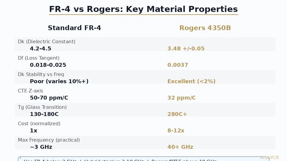
| Dk at 10 GHz | 4.2-4.6 (+/-0.3) | 3.48 (+/-0.05) | Rogers: predictable impedance |
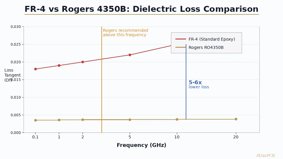
| Loss tangent (Df) | 0.018-0.025 | 0.0037 | Rogers: 5-6x lower loss |
| Dk vs temperature | Shifts 2-5% over range | Shifts <0.5% | Rogers: thermal stability |
| Cost (4L, 100x100mm, qty 10) | $8-15 | $45-80 | FR-4: 5x cheaper |
| Lead time | 5-7 days | 10-15 days | FR-4: faster (stocked) |
| Maximum practical frequency | 2-3 GHz | 40+ GHz | Rogers: RF/mmWave |
| Processing compatibility | Standard | Standard FR-4 press cycles | Tie: both standard |
The one-line answer: If your signal path operates below 2 GHz and you can tolerate +/-10% impedance variation, FR-4 saves money without meaningful performance loss. Above 3 GHz, or anywhere impedance tolerance tighter than +/-7% matters, Rogers is not optional — it is an engineering requirement.
Understanding the Engineering Tradeoffs
The FR-4 versus Rogers decision is not really about “good vs better” — it is about matching material properties to your actual electrical requirements. Engineers who default to Rogers for every board waste money. Engineers who force FR-4 into RF applications waste respins.
The critical difference comes down to three parameters: dielectric constant stability, loss tangent, and moisture absorption. Standard FR-4 is a woven glass-epoxy composite, and its electrical properties are dominated by the resin system and glass weave pattern. The woven structure creates localized Dk variation depending on whether a trace sits over a glass bundle or a resin pocket — a phenomenon called “fiber weave effect” that becomes significant at fine trace widths below 5 mil. Rogers RO4350B uses a ceramic-filled hydrocarbon thermoset that delivers homogeneous dielectric properties regardless of trace position.
In our production line, we regularly see impedance variation of +/-8-12% on FR-4 boards measured at 2.5 GHz, even with tight process control on etch and lamination. The same design on RO4350B consistently measures within +/-3-5%. That difference determines whether your filter passband is where you designed it, or shifted 50 MHz.
The loss tangent difference is equally important for system performance. At 10 GHz over a 50mm trace, FR-4 (Df 0.020) introduces approximately 1.2 dB of dielectric loss per signal layer. Rogers 4350B (Df 0.0037) introduces 0.22 dB — a 5.4x improvement. For a receiver with a -95 dBm sensitivity target, that 1 dB per layer compounds quickly through a multi-layer stackup.
RF MATERIAL EXPERTISE
Not Sure Which Material Fits Your Design?
Our RF engineers review stackup requirements and recommend the right laminate — Rogers, PTFE, or hybrid — based on your frequency, loss budget, and cost target.
Get Material Recommendation ›
Frequency-Dependent Performance: Where FR-4 Breaks Down
The most common mistake we see in designs submitted for fabrication is engineers using FR-4 at frequencies where its loss tangent makes the design unmanufacturable to spec. The issue is not just insertion loss — it is that FR-4’s Dk varies with frequency in a non-linear way that makes impedance prediction unreliable above 3 GHz.
Standard FR-4 epoxy systems absorb moisture (typically 0.1-0.3% by weight under normal conditions), and water has a Dk of approximately 80. Even small moisture uptake shifts the effective Dk enough to move a carefully designed 50-ohm microstrip to 47 or 53 ohms. In a humid environment, this drift is not constant — it changes with ambient conditions, making production repeatability impossible to guarantee.
Rogers hydrocarbon-ceramic materials absorb less than 0.06% moisture, making their electrical properties essentially immune to environmental conditions. This is particularly important for outdoor RF equipment, base station antennas, and automotive radar modules that experience wide temperature and humidity swings over their service life.
For Wi-Fi 6/6E designs operating at 5-6 GHz, we find that high-performance FR-4 variants like Panasonic Megtron 4 (Dk 3.8, Df 0.005) offer an acceptable middle ground — better than standard FR-4 but 60-70% cheaper than Rogers. Above 10 GHz, no FR-4 variant competes with Rogers or PTFE materials in our experience.
Hybrid Stackup Strategy: The Cost-Optimized Approach
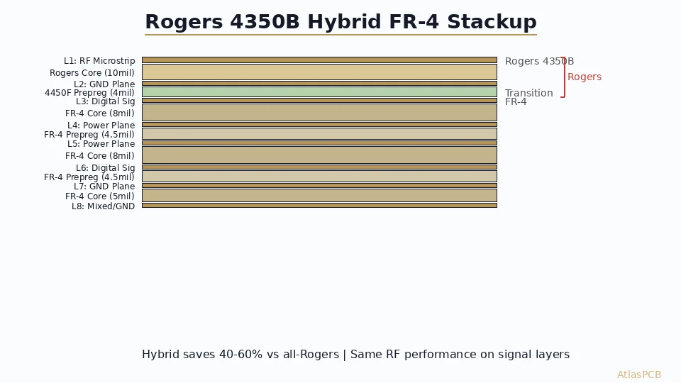
The most practical solution for boards that mix RF and digital functions is a hybrid stackup that places Rogers laminate only where RF signals route, with standard FR-4 for everything else. This approach typically reduces material cost by 40-60% versus an all-Rogers construction while maintaining full RF performance on critical layers.
A typical hybrid construction for a 5G small-cell radio might look like this:
| Layer | Material | Function | Thickness |
|---|---|---|---|
| L1 (Top) | RO4350B | RF antenna feed, PA output | 0.254mm (10 mil) |
| PP1-2 | RO4450F bondply | Bonding layer | 0.100mm |
| L2 | Copper (on FR-4) | Ground plane | 35um |
| Core 2-3 | FR-4 (Tg170) | Digital/power separation | 0.200mm |
| L3 | Copper | Digital signals | 35um |
| PP3-4 | FR-4 prepreg | Standard bonding | 0.180mm |
| L4 (Bot) | Copper on FR-4 | Power plane | 35um |
The key fabrication challenge with hybrid stackups is managing the different CTE (coefficient of thermal expansion) between Rogers and FR-4 materials. RO4350B has a Z-axis CTE of 32 ppm/C, while FR-4 is typically 50-70 ppm/C. This mismatch creates stress at the material interface during thermal cycling. Based on panels we have run across hundreds of hybrid builds, maintaining symmetric construction (Rogers on both outer layers or balanced internal placement) and keeping total board thickness above 1.0mm prevents reliability issues through IPC Class 3 thermal cycling requirements.
HYBRID STACKUP ENGINEERING
Save 40-60% on RF Board Material Cost
We engineer hybrid Rogers/FR-4 stackups optimized for your frequency plan. Upload your design and get a stackup recommendation with impedance modeling.
Processing and Fabrication Considerations
One of Rogers 4350B’s major advantages over traditional PTFE materials is its compatibility with standard FR-4 fabrication processes. Unlike PTFE laminates that require special plasma conditioning, modified drill parameters, and sodium etch treatment for adhesion, RO4350B processes on the same equipment and with the same chemistry as FR-4. This compatibility is why 4350B has become the default choice for production RF boards — it delivers most of PTFE’s electrical performance without the fabrication premium.
However, there are differences that affect yield and cost. Rogers materials are more brittle than FR-4, making mechanical scoring and routing more critical — aggressive depaneling can crack boards near routed edges. Our process engineers set router feed rates 20-30% slower for Rogers panels and maintain minimum 0.5mm clearance from routed edges to the nearest copper feature.
Drilling requires attention as well. Standard FR-4 drill parameters (spindle speed, chip load) work for RO4350B, but the ceramic filler is more abrasive than glass fiber. Drill bit life decreases approximately 40% compared to FR-4, which we account for in tool management to maintain hole quality. Via hole wall roughness directly affects impedance of plated-through vias at high frequency, so maintaining sharp tooling is not just a reliability issue — it is an electrical performance requirement.
For impedance controlled PCBs, the tighter Dk tolerance of Rogers (+/-0.05 vs FR-4’s +/-0.3) means we can hit impedance targets with smaller safety margins. Where an FR-4 design might need a 20% impedance tolerance callout to account for material variation, Rogers allows us to guarantee +/-5% impedance on production panels — a specification that many aerospace and defense programs require.
CHINA RF PCB MANUFACTURER
Rogers, PTFE, and Hybrid — Fabricated In-House
Full material inventory including RO4350B, RO4003C, and PTFE. Impedance controlled to +/-5% with TDR verification on every production lot.
View Capabilities ›Making the Decision: A Practical Framework
After reviewing thousands of RF designs across our production history, we have distilled the FR-4 vs Rogers decision into a practical framework based on three questions:
Question 1: What is your highest operating frequency? Below 1 GHz — FR-4 is fine. 1-3 GHz — evaluate based on impedance tolerance requirement. Above 3 GHz — Rogers or equivalent high-frequency laminate required.
Question 2: What impedance tolerance does your design require? If your system works with +/-10% impedance variation, FR-4 can serve up to 3 GHz. If you need +/-5% or tighter (typical for filters, couplers, matched networks), Rogers is required regardless of frequency.
Question 3: What is your total loss budget? Calculate total insertion loss across all signal layers at your operating frequency. If the FR-4 loss contribution exceeds your budget by more than 2 dB, Rogers is not optional — no amount of amplification downstream fixes a noisy, lossy front-end efficiently.
For teams building their first RF board, we recommend starting with Rogers 4350B in a hybrid stackup. It minimizes cost while eliminating material uncertainty from your first prototype. Once you have validated the design, you can evaluate whether high-performance FR-4 alternatives meet your volume production cost targets — but starting with known-good material properties removes one variable from your debug process.
ATLASPCB
Ready to Quote Your RF Board?
Upload your Gerbers and stackup. We will confirm material availability, model impedance on your actual layer structure, and return a quote with DFM feedback within 24 hours.
Get Instant Quote ›
Reviewed by AtlasPCB Engineering Team — 15+ years in advanced PCB fabrication for RF, HDI, and rigid-flex applications.
Related Reading:
About AtlasPCB — We specialize in complex PCB manufacturing for HDI, RF, and high-reliability applications. Explore our RF and high-frequency PCB services, Rogers RO4350B PCB manufacturing, or get an impedance-controlled PCB manufacturing . Every order includes free engineering review. Get your quote.
Reviewed by AtlasPCB Engineering Team — IPC-certified manufacturing specialists with 15+ years of production experience in HDI, RF, and high-reliability PCB fabrication. Content based on factory floor data and real customer design reviews.
Frequently Asked Questions
At what frequency should I switch from FR-4 to Rogers?
Can I use a hybrid FR-4/Rogers stackup to save cost?
How much more does a Rogers PCB cost compared to FR-4?
What is the dielectric constant of Rogers 4350B vs FR-4?
Is Rogers 4350B or 4003C better for my design?
- FR-4 vs Rogers PCB
- Rogers 4350B
- RF PCB material
- impedance controlled PCB
- high frequency laminate