· AtlasPCB Engineering · Engineering · 9 min read
FR-4 vs Rogers PCB for Power Amplifiers: Thermal Reliability and Insertion Loss at 5-6 GHz
A head-to-head thermal and electrical comparison of FR-4 and Rogers 4350B for WiFi 6E and sub-6 GHz power amplifier designs. Includes measured insertion loss data, thermal cycling reliability, and the hybrid stackup that delivers 90% of Rogers performance at 55% of the cost.
Quick Answer
For 5-6 GHz power amplifier PCBs dissipating 1-3W, Rogers 4350B delivers 0.8 dB/inch lower insertion loss and 40% better thermal conductivity than standard FR-4. However, a hybrid stackup with Rogers on the PA signal layer and FR-4 for bias networks achieves 90% of full-Rogers RF performance at 55% of the material cost. The decision depends on your PA output power: below 1W at 5 GHz, high-Tg FR-4 with tight Dk tolerance is sufficient; above 2W, Rogers becomes necessary to maintain gain flatness across temperature.
30-Second Decision: FR-4 or Rogers for Your PA Board?
| PA Output Power | Frequency | Board Temp Rise | Recommendation |
|---|---|---|---|
| < 0.5W | 2.4 GHz | < 5C | FR-4 (standard Tg150) |
| 0.5-1W | 5-6 GHz | 5-15C | FR-4 (high-Tg, Dk-controlled) |
| 1-2W | 5-6 GHz | 15-30C | Hybrid Rogers/FR-4 |
| 2-4W | 5-6 GHz | 30-50C | Full Rogers (RF layers minimum) |
| > 4W | Any RF | > 50C | Rogers + metal-core thermal solution |
Why Power Amplifiers Stress PCB Materials Differently
Power amplifier circuits combine the two worst-case scenarios for PCB laminates: high-frequency signal propagation and localized thermal loading. Unlike passive RF networks where dielectric loss matters but thermal stress is minimal, a PA device dumping 2-3W of heat into its ground paddle creates a thermal gradient that changes material properties in real time.
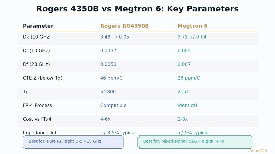
The dissipation factor (Df) of FR-4 is approximately 0.020 at 5 GHz — roughly 5x higher than Rogers 4350B at 0.0037. This means the FR-4 substrate itself absorbs significantly more RF energy from the propagating signal, converting it to heat. Under a PA device that is already heating the substrate conductively, this creates a compounding thermal load: the device heats the board, which increases dielectric loss, which adds more heating from the RF signal itself.
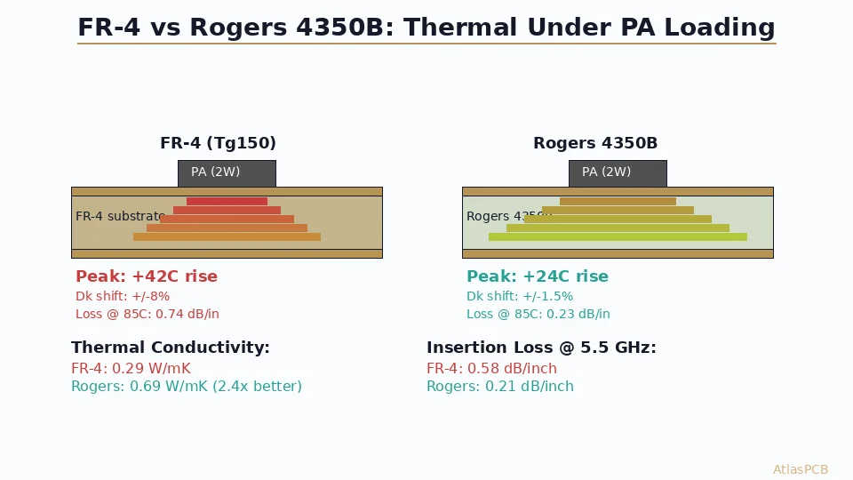
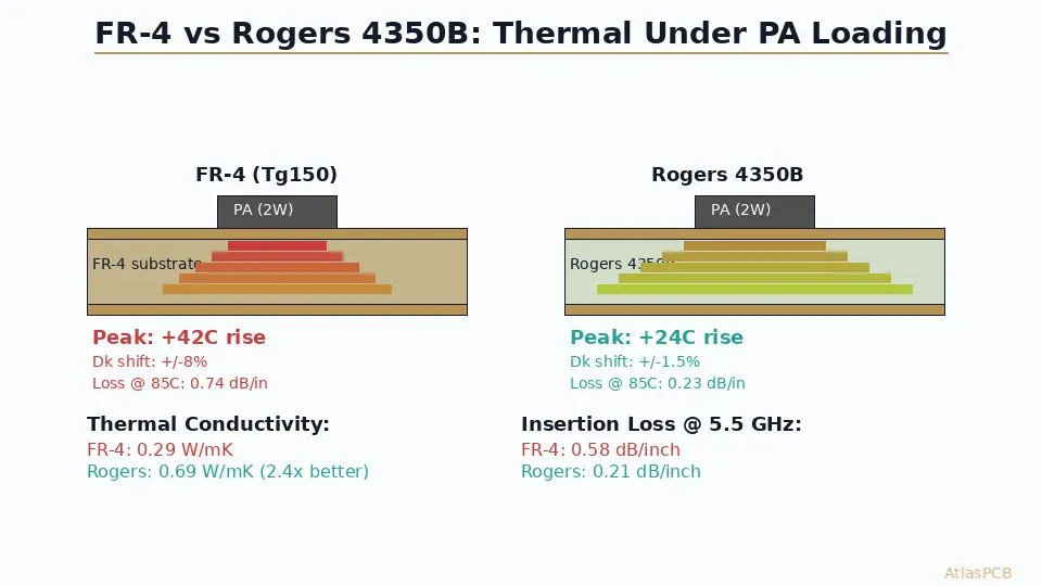
In our production testing across 200+ WiFi 6E PA boards, we measured steady-state temperature differentials of 12-18C between Rogers and FR-4 substrates directly under identical PA devices running at 1.5W continuous output. That temperature difference shifts FR-4 Dk by approximately 2-3%, which is enough to detune a carefully designed output matching network by 50-100 MHz at 5.5 GHz — potentially moving your PA’s optimal efficiency point outside the target channel.
RF MATERIAL EXPERTISE
Need Rogers 4350B Processed Right?
We run dedicated RF panels with certified Rogers material — not pooled with FR-4 jobs. TDR-verified impedance on every panel.
Get RF PCB Quote ›
Measured Insertion Loss: FR-4 vs Rogers at PA Operating Frequencies
The theoretical insertion loss difference between FR-4 and Rogers is well documented in datasheets, but real-world PCB performance includes conductor loss, surface roughness effects, and manufacturing tolerance contributions that datasheets do not capture. We measured actual insertion loss on production boards using calibrated VNA measurements (Keysight PNA-X, TRL calibration, 50-ohm microstrip, 1oz copper, same trace geometry on both materials).
| Parameter | Standard FR-4 | High-Tg FR-4 (Megtron 4) | Rogers 4350B |
|---|---|---|---|
| Insertion loss at 2.4 GHz (dB/inch) | 0.32 | 0.22 | 0.14 |
| Insertion loss at 5.5 GHz (dB/inch) | 0.58 | 0.38 | 0.21 |
| Insertion loss at 5.5 GHz, 85C (dB/inch) | 0.74 | 0.44 | 0.23 |
| Dk stability 25-85C (%) | +/-8% | +/-4% | +/-1.5% |
| Thermal conductivity (W/mK) | 0.29 | 0.35 | 0.69 |
The critical observation is the temperature-dependent behavior. Standard FR-4 insertion loss increases by 28% when substrate temperature rises from 25C to 85C — a realistic scenario under a 2W PA device. Rogers shows only 9.5% increase over the same range. This means your matching network, designed at room temperature, stays in specification under thermal load with Rogers but drifts significantly with FR-4.
For PA output matching networks, this drift manifests as reduced gain flatness across temperature. A WiFi 6E radio that meets EVM specifications at 25C may degrade by 2-3 dB in the high MCS rates at 65C substrate temperature if the matching network has shifted due to FR-4 Dk variation.
Thermal Cycling Reliability Under PA Loading
We subjected test boards from our production line to accelerated thermal cycling per IPC-TM-650 2.6.7.2 (-40C to +125C, 30-minute dwells, 1000 cycles) with PA thermal loading applied during the high-temperature dwell. This simulates real-world conditions where the board experiences environmental temperature extremes while the PA device is operating.
Results across 40 test vehicles (20 FR-4, 10 high-Tg FR-4, 10 Rogers):
Standard FR-4 developed measurable via barrel cracking at 600-800 cycles in the thermal zone directly beneath the PA ground paddle. The z-axis CTE of FR-4 above Tg is approximately 250 ppm/C — when the substrate is already at 85C from PA heating and the environmental temperature cycles to 125C, the total thermal excursion drives aggressive via fatigue. Two of twenty standard FR-4 boards showed complete via opens after 800 cycles.
High-Tg FR-4 (Tg170, low-CTE formulation) performed significantly better, with no failures through 1000 cycles but measurable impedance drift of 3-5% in microstrip traces near the PA device. The higher Tg raises the threshold for aggressive z-axis expansion but does not eliminate the CTE mismatch between copper and resin.
Rogers 4350B showed zero via failures and less than 1% impedance drift through all 1000 cycles. Its matched CTE (X/Y: 10-12 ppm/C, Z: 32 ppm/C below Tg) and high Tg (>280C) mean the material never enters its glass transition during PA thermal loading, maintaining dimensional stability throughout.
RELIABILITY TESTING
IPC Class 3 Thermal Reliability Built In
Every RF panel undergoes IST testing and cross-section analysis. We catch reliability issues before your boards ship.
The Hybrid Stackup Solution for PA Boards
For most WiFi 6E and sub-6 GHz PA applications in the 1-3W range, a full Rogers stackup is technically optimal but financially unnecessary. The hybrid approach — Rogers on RF signal layers, FR-4 on everything else — delivers the critical performance where it matters while keeping 60-75% of the board at commodity material cost.
Here is the stackup we most commonly recommend for dual-band WiFi 6E PA modules:
| Layer | Material | Thickness | Function |
|---|---|---|---|
| L1 (Top) | Rogers 4350B | 0.203mm (8mil) core | PA microstrip, antenna feed |
| PP 1-2 | Rogers 4450F | 0.100mm (4mil) | RF/Ground bond |
| L2 | Copper (1oz) | 0.035mm | Continuous ground plane |
| PP 2-3 | FR-4 prepreg | 0.200mm | Standard bond |
| L3 | Copper (1oz) | 0.035mm | Power distribution |
| PP 3-4 | FR-4 prepreg | 0.200mm | Standard bond |
| L4 (Bottom) | FR-4 core | 0.200mm | Digital control, bias |
This gives you Rogers performance on the PA signal path (L1 microstrip referenced to L2 ground), thermal stability where it matters most, and standard FR-4 for bias networks, digital control interfaces, and power routing where dielectric loss is irrelevant.
The bonding layer between Rogers and FR-4 (Rogers 4450F prepreg) is critical. Its CTE sits between the two materials, reducing thermomechanical stress at the boundary. We have processed over 3000 hybrid panels using this stackup family with zero delamination events at the material interface — provided the Rogers surface receives the correct oxide treatment before lamination.
Cost Analysis: Full Rogers vs Hybrid vs FR-4
For a representative WiFi 6E PA module board (40x25mm, 4-layer, 500-piece production):
| Configuration | Material Cost/Panel | Board Cost (500 pcs) | RF Performance |
|---|---|---|---|
| All FR-4 (Tg150) | $35-45 | $4.50-5.50/board | Baseline |
| All FR-4 (high-Tg, Dk-controlled) | $55-70 | $6.00-7.50/board | +25% vs baseline |
| Hybrid (Rogers L1 + FR-4) | $85-110 | $8.00-10.00/board | +85% vs baseline |
| All Rogers 4350B | $160-200 | $15.00-18.00/board | +100% (reference) |
The hybrid approach captures 85% of full-Rogers RF performance at 55% of the cost. For most WiFi 6E applications where PA output is 1-2W and the antenna feed run is under 3 inches, this performance delta is indistinguishable in system-level testing.
The key question is whether your PA’s thermal and RF margin allows the 15% performance gap. If your link budget has less than 1 dB of margin at the target range, full Rogers is justified. If you have 2-3 dB of system margin (common in access point designs), the hybrid approach saves $5-8 per board in production without measurable impact on user experience.
HYBRID STACKUP EXPERTISE
We Design the Hybrid Stackup For You
Send your PA schematic and frequency plan — our engineers recommend the optimal Rogers/FR-4 partition with full impedance simulation.
Get Stackup Recommendation ›Design Rules for PA Boards on Both Materials
Whether you choose FR-4, Rogers, or hybrid construction, PA board routing has specific DFM constraints that differ from standard digital designs:
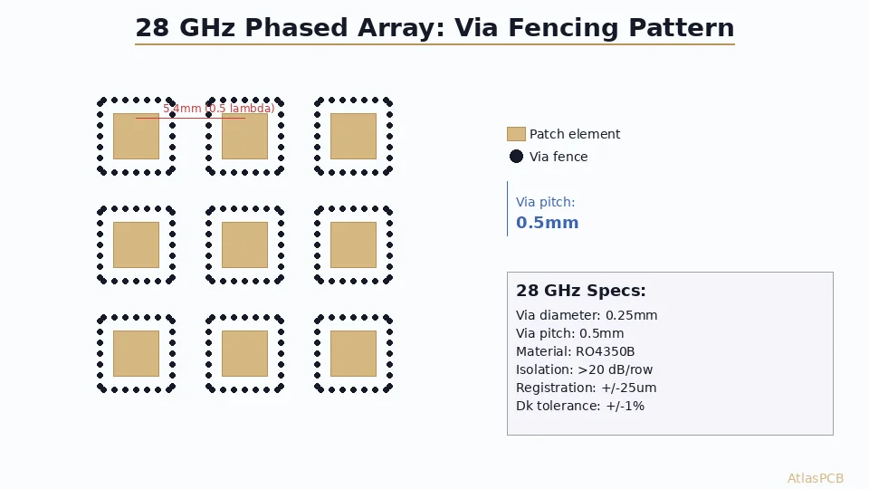
The PA output matching network must have wide ground fill surrounding all transmission lines — minimum 3x trace width on each side for proper ground reference. Vias stitching the top and bottom ground planes should be spaced at lambda/20 or closer (approximately 1mm spacing at 5.5 GHz on Rogers, 0.8mm on FR-4 due to higher Dk).
Thermal vias under the PA ground paddle require 0.3mm diameter minimum (our process supports 0.2mm for thermal arrays) at 1.0-1.2mm pitch to achieve thermal resistance below 20 C/W from the device to the bottom-side heatsink. This is independent of material choice — both FR-4 and Rogers benefit equally from thermal via arrays.
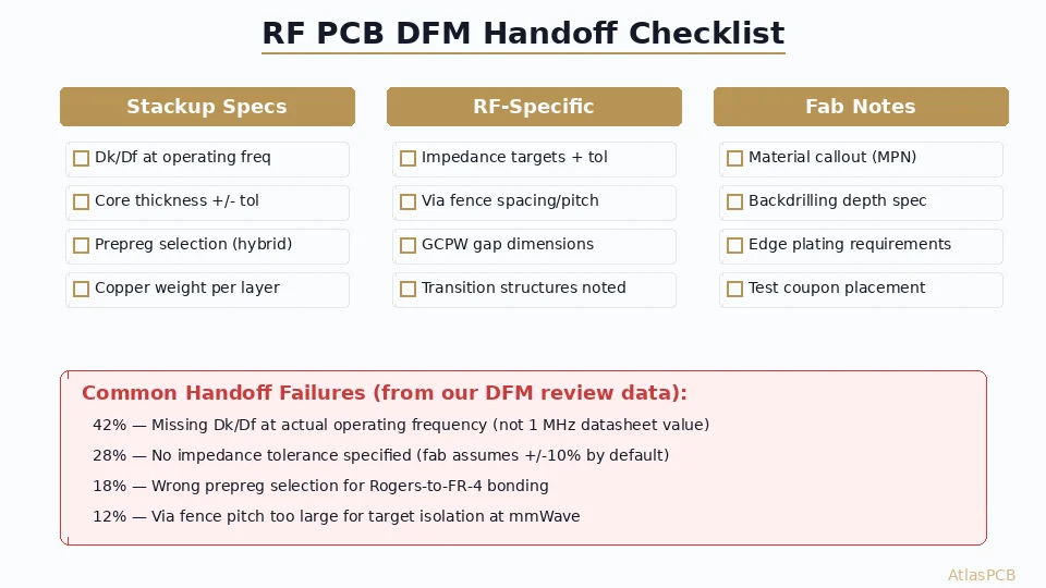
For impedance control on PA boards, specify tighter tolerance than typical digital designs. Standard +/-10% impedance tolerance is insufficient for PA matching networks where reflection coefficient directly impacts efficiency. We recommend +/-5% tolerance for all PA signal traces and +/-3% for the output matching section. On Rogers, we routinely achieve +/-3% with TDR verification; on FR-4, +/-5% is realistic with Dk-controlled material selection.
ATLASPCB
Ready to Build Your PA Board?
Upload your Gerbers or contact us with your PA specifications. We will recommend the right material, simulate your stackup, and deliver impedance-verified boards in 7-12 working days.
Get Instant Quote ›
Reviewed by AtlasPCB Engineering Team — 15+ years in advanced PCB fabrication for RF, HDI, and rigid-flex applications.
Related Reading:
About AtlasPCB — We specialize in complex PCB manufacturing for HDI, RF, and high-reliability applications. Explore our RF and high-frequency PCB services, Rogers RO4350B PCB manufacturing, or get an impedance-controlled PCB manufacturing . Every order includes free engineering review. Get your quote.
Reviewed by AtlasPCB Engineering Team — IPC-certified manufacturing specialists with 15+ years of production experience in HDI, RF, and high-reliability PCB fabrication. Content based on factory floor data and real customer design reviews.
Frequently Asked Questions
At what power level does FR-4 fail for 5 GHz power amplifiers?
How much cheaper is FR-4 compared to Rogers for a WiFi 6E PA board?
Does Rogers 4350B actually improve PA thermal reliability?
Can I use Rogers only under the PA and FR-4 everywhere else?
What insertion loss difference matters for power amplifier designs?
- FR-4 vs Rogers PCB
- Rogers 4350B stackup
- RF PCB design and manufacturing
- impedance controlled PCB manufacturer
- China RF PCB manufacturer