· AtlasPCB Engineering · Engineering · 9 min read
FR-4 vs Rogers PCB for 77 GHz Automotive Radar: Why ADAS Demands Low-Loss Laminates
At 77 GHz, standard FR-4 introduces 2.8 dB/cm insertion loss — making it physically unusable for automotive radar. This guide quantifies exactly where FR-4 fails, which Rogers variants work for ADAS, and how hybrid stackups cut cost while maintaining radar performance.
Quick Answer
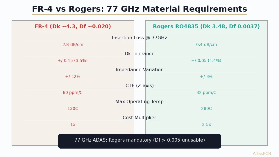
FR-4 cannot be used for 77 GHz automotive radar antenna layers. Its dissipation factor (Df 0.020) produces 2.8 dB/cm insertion loss at 77 GHz versus 0.4 dB/cm for Rogers RO4835 (Df 0.0037). For ADAS radar, use Rogers RO4835 or RO3003 for antenna/feed network layers, with FR-4 acceptable only for digital baseband layers in a hybrid stackup configuration.
The 30-Second Answer
| Parameter | Standard FR-4 | Rogers RO4835 | Impact at 77 GHz |
|---|---|---|---|
| Dk | 4.2-4.5 | 3.48 +/-0.05 | FR-4 variation causes +/-12% impedance shift |
| Df (Loss tangent) | 0.018-0.022 | 0.0037 | FR-4 = 2.8 dB/cm loss; Rogers = 0.4 dB/cm |
| Dk tolerance | +/-0.15 | +/-0.05 | Radar beamforming requires tight phase matching |
| CTE Z-axis | 55-65 ppm/C | 32 ppm/C | Thermal cycling reliability for automotive (-40 to +125C) |
| Moisture absorption | 0.15% | 0.06% | Dk drift in humidity affects radar calibration |
| Cost multiplier | 1x | 3-5x | Offset by hybrid stackup strategy |
Bottom line: At 77 GHz, FR-4 is not a design choice — it is a physical impossibility. The dielectric loss alone eliminates it from consideration for any radar antenna or feed network layer. The only engineering question is which low-loss laminate to select and whether a hybrid stackup can reduce cost.
Why 77 GHz Breaks FR-4 Completely
The relationship between frequency and dielectric loss is not linear — it accelerates. At 2.4 GHz, FR-4’s Df of 0.020 produces a manageable 0.15 dB/cm insertion loss, and many WiFi designs work perfectly well on standard laminate. Engineers who have successfully used FR-4 for sub-6 GHz RF sometimes assume it might work at millimeter-wave frequencies with careful layout. It cannot.
At 77 GHz, the insertion loss calculation becomes brutal. Using the standard microstrip loss formula, conductor loss (alpha_c) contributes approximately 0.8 dB/cm on a 50-ohm line with 0.5 oz copper, but dielectric loss (alpha_d) dominates at 2.0 dB/cm for FR-4 Df = 0.020. Combined, that is 2.8 dB/cm total insertion loss. A typical 77 GHz patch antenna feed network on an automotive radar module runs 4-6 cm from the MMIC to the antenna element — meaning 11-17 dB of signal vanishes before reaching the antenna.
For context, a modern 77 GHz MMIC like the Infineon AURIX radar chipset outputs approximately +12 dBm. After connector transitions, matching networks, and the feed network, you need at least +5 dBm at the antenna to achieve the 150-200 meter detection range required for automotive forward-facing radar. Losing 11-17 dB in the feed network alone makes this impossible. Rogers RO4835 at 0.4 dB/cm produces only 1.6-2.4 dB feed network loss over the same distance — well within the link budget.
AUTOMOTIVE RADAR PCB EXPERTISE
77 GHz Radar Board Manufacturing
Rogers RO4835/RO3003 processing with +/-5% impedance control. Automotive-qualified to AEC-Q100 thermal cycling requirements.
Get RF PCB Quote ›
Rogers Material Options for 77 GHz ADAS
Not all Rogers materials are equal at millimeter-wave frequencies. The choice between RO4835, RO3003, and RO4350B depends on your specific radar architecture, production volume, and thermal requirements.
Rogers RO4835 has emerged as the industry workhorse for 77 GHz automotive radar. Its thermoset-based construction processes similarly to FR-4 — standard drill bits, standard oxide treatments, standard lamination pressures — which keeps fabrication costs and cycle times reasonable. The Df of 0.0037 at 77 GHz delivers excellent loss performance while the Dk tolerance of +/-0.05 provides the phase consistency needed for beamforming arrays. In our production experience, RO4835 achieves consistent impedance control within +/-3% at 77 GHz when paired with proper prepreg selection and controlled etching.
Rogers RO3003 offers the lowest loss available in a thermoset PTFE laminate (Df 0.0013 at 77 GHz). This material is specified for long-range forward-facing radar where every 0.1 dB matters — particularly cascaded MIMO architectures with 12+ antenna elements and feed networks exceeding 8 cm. However, RO3003 requires specialized PTFE processing: sodium-etch surface treatment for adhesion, modified drill parameters to prevent smearing, and controlled lamination temperature profiles. These processing requirements add approximately 40% to fabrication cost versus RO4835.
Rogers RO4350B, while extensively used at sub-6 GHz frequencies, works at 77 GHz but with limitations. Its Dk of 3.66 (versus 3.48 for RO4835) narrows the achievable trace widths for 50-ohm lines, making manufacturing tolerance tighter. For simpler radar architectures with short feed networks (under 3 cm), RO4350B provides adequate performance at lower material cost than RO4835. We typically recommend it for parking sensors and short-range corner radar where path loss budget is generous.
The Hybrid Stackup Strategy: RF Performance at Reduced Cost
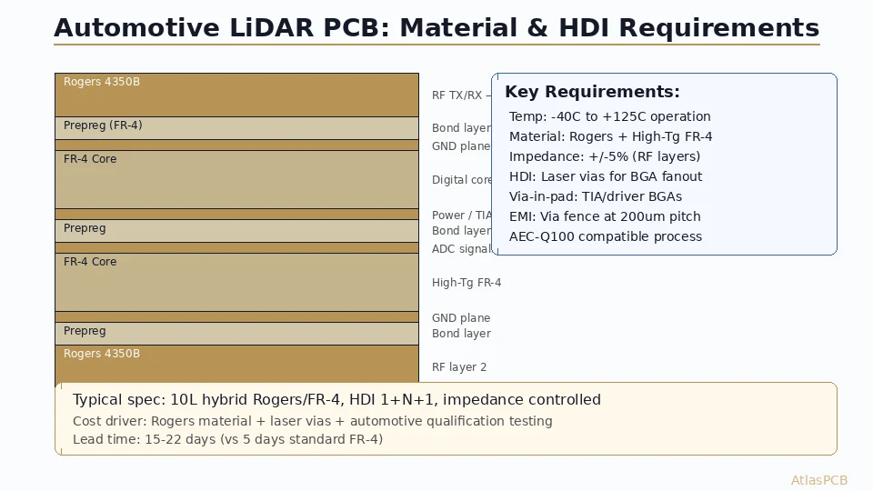
The most cost-effective approach for 77 GHz automotive radar uses a hybrid stackup: Rogers material only on the layers carrying RF signals, with standard high-Tg FR-4 for digital baseband, power distribution, and mechanical support. This approach reduces material cost by 40-60% versus an all-Rogers construction while maintaining identical RF performance on the antenna and feed network layers.
A typical 6-layer hybrid stackup for a 77 GHz radar module looks like this:
| Layer | Material | Function | Thickness |
|---|---|---|---|
| L1 | Rogers RO4835 (5 mil) | Patch antenna array | 0.127 mm |
| PP1 | Rogers 4450F bondply | RF bonding | 0.100 mm |
| L2 | Copper | Ground reference (RF) | 35 um |
| Core | FR-4 High-Tg (10 mil) | Digital routing | 0.254 mm |
| L3 | Copper | Power/signal | 35 um |
| PP2 | FR-4 prepreg 2116 | Bonding | 0.120 mm |
| L4 | Copper | Ground | 35 um |
| Core | FR-4 High-Tg (10 mil) | Mechanical | 0.254 mm |
| L5 | Copper | Signal/power | 35 um |
| PP3 | Rogers 4450F bondply | RF bonding | 0.100 mm |
| L6 | Rogers RO4835 (5 mil) | Feed network | 0.127 mm |
The critical detail is the bonding interface between Rogers and FR-4 layers. Standard FR-4 prepreg cannot reliably bond to Rogers PTFE-based surfaces. Rogers 4450F bondply (Dk 3.52, Df 0.004) provides a compatible bonding layer that maintains impedance continuity at the transition. We have seen fabrication failures when shops attempt to use standard 2116 prepreg against Rogers layers — delamination occurs at thermal cycling within 200-500 cycles, well below automotive qualification requirements.
HYBRID STACKUP ENGINEERING
Rogers + FR-4 Hybrid Construction
Our process engineers optimize hybrid stackups for RF performance and thermal reliability. Free stackup review with every RF quote.
Fabrication Challenges Specific to 77 GHz Radar Boards
Manufacturing PCBs for 77 GHz automotive radar introduces process requirements that separate capable RF fabricators from standard PCB shops attempting to quote Rogers material.
Etching uniformity becomes critical because trace widths for 50-ohm microstrip on 5-mil RO4835 are approximately 0.30 mm (12 mil). At 77 GHz, a +/-0.5 mil variation in trace width causes approximately +/-3% impedance change. Standard etching processes targeting +/-1.0 mil tolerance are insufficient — you need a fabricator with controlled spray etching and inline measurement capable of +/-0.5 mil or better. In our facility, we achieve this through modified etchant chemistry (ammoniacal copper at controlled temperature and pH) with laser-based inline width measurement at 100% panel inspection.
Registration accuracy matters for via-to-pad alignment on antenna feed networks. A typical 77 GHz patch antenna has a feed via connecting from the ground layer to the radiating patch, with a pad diameter of 0.4-0.5 mm. Layer-to-layer misregistration exceeding 50 um can shift the via off-center enough to create asymmetric coupling, degrading antenna gain by 1-2 dB. Standard registration of +/-75 um is marginal — premium registration of +/-25-50 um is required.
Surface finish selection also affects 77 GHz performance. ENIG (electroless nickel/immersion gold) introduces a ferromagnetic nickel layer that increases conductor loss at millimeter-wave frequencies by approximately 0.2 dB/cm compared to bare copper. For best performance, immersion silver or OSP is preferred for the RF layers, with ENIG used only on assembly pads where solderability matters. Some designs split the surface finish — immersion silver on the antenna side, ENIG on the component assembly side — though this adds processing cost.
Automotive Qualification: Beyond RF Performance
A 77 GHz radar PCB that works perfectly on the bench may fail in the field if it was not manufactured with automotive-grade process controls. AEC-Q100 qualification for the radar module subjects the PCB to:
- Thermal cycling: -40C to +125C, 1000 cycles minimum
- Humidity: 85C/85% RH, 1000 hours
- Vibration: 10-2000 Hz sweep, 30g peak acceleration
- Thermal shock: -40C to +150C, 5-minute transitions
FR-4/Rogers hybrid stackups face particular stress at the material interface during thermal cycling. The CTE mismatch between FR-4 (55-65 ppm/C Z-axis) and Rogers (32 ppm/C) creates shear stress at the bondply interface. Proper design mitigates this through symmetric stackup construction, controlled bond-ply thickness, and copper balance between layers. We routinely process 77 GHz radar boards that pass 2000 thermal cycles without delamination when the stackup follows our validated construction rules.
AUTOMOTIVE QUALIFIED PROCESS
-40C to +125C Thermal Cycling Tested
Hybrid Rogers/FR-4 stackups validated to 2000+ cycles. Full material traceability and lot-level documentation for IATF 16949.
Request Automotive Quote ›Cost Comparison and Volume Considerations
| Configuration | 5pc Prototype | 100pc Production | 1000pc Volume |
|---|---|---|---|
| Full Rogers RO4835 (4L) | $180-280/board | $45-70/board | $18-30/board |
| Hybrid Rogers/FR-4 (6L) | $120-180/board | $30-50/board | $12-22/board |
| Full FR-4 equivalent (4L) | $35-50/board | $8-15/board | $4-8/board |
The hybrid approach offers 30-40% savings over full Rogers construction at production volumes while maintaining identical RF performance on antenna layers. For cost-sensitive applications like parking sensors (short range, simple antenna), even thinner Rogers layers (3 mil) or lower-grade PTFE materials can further reduce cost.
At volumes above 5000 pieces per month — typical for automotive Tier 1 suppliers — the material cost advantage of hybrid stackups compounds significantly. We process radar boards for multiple automotive programs where the hybrid construction saves $3-8 per board versus full Rogers, translating to $15,000-40,000 per month in material cost reduction.
ATLASPCB
Ready to Design Your 77 GHz Radar Board?
Upload your stackup or Gerber files. Our RF engineers review material selection and impedance modeling within 24 hours — included with every quote.
Get Instant Quote ›
Reviewed by AtlasPCB Engineering Team — 15+ years in advanced PCB fabrication for RF, HDI, and rigid-flex applications.
Related Reading:
About AtlasPCB — We specialize in complex PCB manufacturing for HDI, RF, and high-reliability applications. Explore our RF and high-frequency PCB services, Rogers RO4350B PCB manufacturing, or get an multilayer PCB fabrication up to 30 layers . Every order includes free engineering review. Get your quote.
Reviewed by AtlasPCB Engineering Team — IPC-certified manufacturing specialists with 15+ years of production experience in HDI, RF, and high-reliability PCB fabrication. Content based on factory floor data and real customer design reviews.
Frequently Asked Questions
Can I use FR-4 for a 77 GHz automotive radar PCB?
Which Rogers material is best for 77 GHz radar?
How much does a 77 GHz radar PCB cost compared to standard FR-4?
What impedance tolerance is required for 77 GHz automotive radar?
- FR-4 vs Rogers PCB
- automotive radar PCB
- 77 GHz
- ADAS
- Rogers 4350B stackup
- RF PCB design and manufacturing